Cirkit Designer Logo
Cirkit Designer
Your all-in-one circuit design IDE
Home / 
Component Documentation

How to Use Adafruit Feather 32u4 RFM69: Examples, Pinouts, and Specs

Image of Adafruit Feather 32u4 RFM69
Cirkit Designer LogoDesign with Adafruit Feather 32u4 RFM69 in Cirkit Designer

Introduction

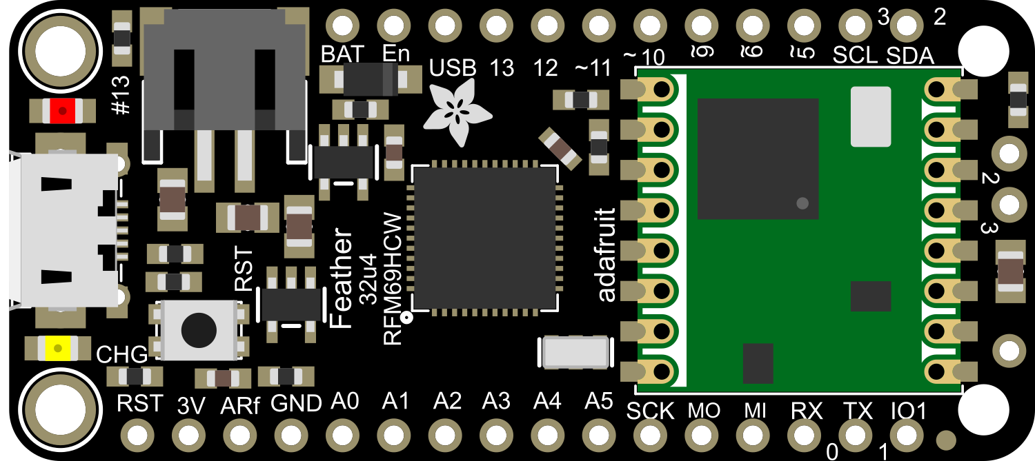
The Adafruit Feather 32u4 RFM69 is a powerful and versatile microcontroller board that integrates a high-performance ATmega32u4 MCU with a RFM69HCW radio module for wireless communication. This board is part of the Feather ecosystem, designed for portability, ease of use, and expandability. It is ideal for hobbyists, educators, and professionals who require a compact, reliable, and energy-efficient solution for IoT projects, wireless sensors, and remote-controlled devices.

Explore Projects Built with Adafruit Feather 32u4 RFM69

Use Cirkit Designer to design, explore, and prototype these projects online. Some projects support real-time simulation. Click "Open Project" to start designing instantly!
Dual-Mode LoRa and GSM Communication Device with ESP32
Image of modul gateway: A project utilizing Adafruit Feather 32u4 RFM69 in a practical application
This circuit features an ESP32 Devkit V1 microcontroller interfaced with an RFM95 LoRa transceiver module for long-range communication and a SIM800L GSM module for cellular connectivity. Two LM2596 step-down modules are used to regulate the 12V battery voltage down to 3.3V required by the ESP32, RFM95, and SIM800L. The ESP32 facilitates data exchange between the RFM95 and SIM800L, enabling the system to send/receive data over both LoRa and GSM networks.
Cirkit Designer LogoOpen Project in Cirkit Designer
Biometric and RFID Security System with Dual Adafruit Feather nRF52840 Controllers
Image of Rfid access control: A project utilizing Adafruit Feather 32u4 RFM69 in a practical application
This circuit features two Adafruit Feather nRF52840 microcontrollers, each interfaced with an RFID-RC522 module for RFID communication and an AT24C256 external EEPROM for additional memory storage. One of the microcontrollers is also connected to an R307 Fingerprint Sensor for biometric input, and both microcontrollers are powered by a shared power supply and a coin cell breakout for backup or RTC power. The circuit is likely designed for secure access control or identification purposes, utilizing both RFID and fingerprint authentication, with data storage capabilities.
Cirkit Designer LogoOpen Project in Cirkit Designer
ESP32-Based RF Communication System with 433 MHz Modules
Image of 433 mhz: A project utilizing Adafruit Feather 32u4 RFM69 in a practical application
This circuit comprises an ESP32 microcontroller connected to a 433 MHz RF transmitter and receiver pair. The ESP32 is programmed to receive and decode RF signals through the receiver module, as well as send RF signals via the transmitter module. Additionally, the ESP32 can communicate with a Bluetooth device to exchange commands and data, and it uses an LED for status indication.
Cirkit Designer LogoOpen Project in Cirkit Designer
433 MHz RF Transmitter and Receiver with Arduino Uno for Wireless LED Control
Image of rf module up: A project utilizing Adafruit Feather 32u4 RFM69 in a practical application
This circuit consists of two Arduino Uno R3 microcontrollers communicating wirelessly using 433 MHz RF modules. One Arduino is connected to an RF transmitter to send data, while the other Arduino is connected to an RF receiver to receive data and control an LED based on the received signal.
Cirkit Designer LogoOpen Project in Cirkit Designer

Explore Projects Built with Adafruit Feather 32u4 RFM69

Use Cirkit Designer to design, explore, and prototype these projects online. Some projects support real-time simulation. Click "Open Project" to start designing instantly!
Image of modul gateway: A project utilizing Adafruit Feather 32u4 RFM69 in a practical application
Dual-Mode LoRa and GSM Communication Device with ESP32
This circuit features an ESP32 Devkit V1 microcontroller interfaced with an RFM95 LoRa transceiver module for long-range communication and a SIM800L GSM module for cellular connectivity. Two LM2596 step-down modules are used to regulate the 12V battery voltage down to 3.3V required by the ESP32, RFM95, and SIM800L. The ESP32 facilitates data exchange between the RFM95 and SIM800L, enabling the system to send/receive data over both LoRa and GSM networks.
Cirkit Designer LogoOpen Project in Cirkit Designer
Image of Rfid access control: A project utilizing Adafruit Feather 32u4 RFM69 in a practical application
Biometric and RFID Security System with Dual Adafruit Feather nRF52840 Controllers
This circuit features two Adafruit Feather nRF52840 microcontrollers, each interfaced with an RFID-RC522 module for RFID communication and an AT24C256 external EEPROM for additional memory storage. One of the microcontrollers is also connected to an R307 Fingerprint Sensor for biometric input, and both microcontrollers are powered by a shared power supply and a coin cell breakout for backup or RTC power. The circuit is likely designed for secure access control or identification purposes, utilizing both RFID and fingerprint authentication, with data storage capabilities.
Cirkit Designer LogoOpen Project in Cirkit Designer
Image of 433 mhz: A project utilizing Adafruit Feather 32u4 RFM69 in a practical application
ESP32-Based RF Communication System with 433 MHz Modules
This circuit comprises an ESP32 microcontroller connected to a 433 MHz RF transmitter and receiver pair. The ESP32 is programmed to receive and decode RF signals through the receiver module, as well as send RF signals via the transmitter module. Additionally, the ESP32 can communicate with a Bluetooth device to exchange commands and data, and it uses an LED for status indication.
Cirkit Designer LogoOpen Project in Cirkit Designer
Image of rf module up: A project utilizing Adafruit Feather 32u4 RFM69 in a practical application
433 MHz RF Transmitter and Receiver with Arduino Uno for Wireless LED Control
This circuit consists of two Arduino Uno R3 microcontrollers communicating wirelessly using 433 MHz RF modules. One Arduino is connected to an RF transmitter to send data, while the other Arduino is connected to an RF receiver to receive data and control an LED based on the received signal.
Cirkit Designer LogoOpen Project in Cirkit Designer

Common Applications and Use Cases

  • Internet of Things (IoT) devices
  • Wireless sensor networks
  • Home automation systems
  • Remote control applications
  • Educational projects and prototyping

Technical Specifications

Key Technical Details

  • Microcontroller: ATmega32u4
  • Operating Voltage: 3.3V
  • Input Voltage: 3.7-6V via battery and up to 12V via USB
  • Clock Speed: 8 MHz
  • Digital I/O Pins: 20
  • PWM Channels: 7
  • Analog Input Channels: 12
  • DC Current per I/O Pin: 40 mA
  • Flash Memory: 32 KB (ATmega32u4) of which 4 KB used by bootloader
  • SRAM: 2.5 KB (ATmega32u4)
  • EEPROM: 1 KB (ATmega32u4)
  • Radio Frequency: 915 MHz (RFM69HCW)
  • Transmit Power: +13 to +20 dBm

Pin Configuration and Descriptions

Pin Number Function Description
1 GND Ground
2 BAT Battery positive voltage (3.7-6V)
3 EN Enable pin for the 3.3V regulator
4 USB USB positive voltage (up to 12V)
5 RST Reset pin
6-11 D0-D5 Digital I/O pins, PWM capable (D3, D5)
12-17 D6-D11 Digital I/O pins, PWM capable (D9, D10, D11)
18-19 D12-D13 Digital I/O pins, D13 is also the LED_BUILTIN
20-25 A0-A5 Analog input channels
26-27 SDA/SCL I2C Data/Clock
28-29 RX/TX UART Receive/Transmit
30 MISO SPI Master In Slave Out
31 SCK SPI Serial Clock
32 MOSI SPI Master Out Slave In
33 RST Radio module reset
34 CS Radio module chip select
35 G0 Radio module interrupt/GPIO0

Usage Instructions

How to Use the Component in a Circuit

  1. Powering the Board:

    • Connect a 3.7V Lithium polymer battery to the JST connector for portable applications.
    • Alternatively, power the board via the USB connection.
  2. Programming:

    • Connect the board to a computer using a micro-USB cable.
    • Select "Adafruit Feather 32u4" from the Arduino IDE's Tools > Board menu.
  3. Using the RFM69 Radio:

    • Install the RadioHead library in the Arduino IDE to use the RFM69 module.
    • Connect an antenna to the board's antenna pad to ensure proper RF performance.

Important Considerations and Best Practices

  • Always disconnect the battery before soldering to the board.
  • Ensure that the antenna is properly connected and suited for the 915 MHz frequency.
  • Avoid placing the board near metal objects or inside metal enclosures, which can interfere with radio signals.
  • Use capacitors to filter noise if the board is used in a noisy power environment.

Troubleshooting and FAQs

Common Issues

  • Board not recognized by computer:

    • Ensure the micro-USB cable is data-capable.
    • Press the reset button twice quickly to enter bootloader mode.
  • Radio communication not working:

    • Check that the antenna is properly connected.
    • Verify that the RadioHead library is correctly installed and configured.

Solutions and Tips for Troubleshooting

  • If the board is not powering on, check the battery and USB connections.
  • For radio range issues, ensure there are no obstructions and that the antenna is optimal for the frequency used.
  • Use the onboard LED to debug your code and signal status.

FAQs

  • Can I use the Feather 32u4 RFM69 with a 5V system?

    • No, the board operates at 3.3V. Level shifting is required for 5V systems.
  • How do I charge the battery?

    • The board includes a built-in LiPo charger. Simply connect the board to USB power with the battery attached.
  • What is the range of the RFM69 radio?

    • The range can vary from a few hundred meters to over a kilometer, depending on the environment and antenna.

Example Code for Arduino UNO

#include <SPI.h>
#include <RH_RF69.h>

// Singleton instance of the radio driver
RH_RF69 rf69;

void setup() {
  // Initialize RFM69 radio
  if (!rf69.init()) {
    // Initialization failed, handle the error
  }
  // Set the frequency to match your module (e.g., 915.0 for North America)
  if (!rf69.setFrequency(915.0)) {
    // Frequency set failed, handle the error
  }
  // Optionally, increase the transmit power
  rf69.setTxPower(14, true);
}

void loop() {
  // Send a message to a receiver
  const char *msg = "Hello World!";
  rf69.send((uint8_t *)msg, strlen(msg));
  rf69.waitPacketSent();

  // Now wait for a reply
  uint8_t buf[RH_RF69_MAX_MESSAGE_LEN];
  uint8_t len = sizeof(buf);

  if (rf69.waitAvailableTimeout(500)) {
    // Should be a reply message for us now
    if (rf69.recv(buf, &len)) {
      // Message received, handle it
    } else {
      // Receive failed, handle the error
    }
  }
}

Note: This example assumes that you have the RadioHead library installed and that you are familiar with uploading sketches to the Adafruit Feather 32u4 RFM69. The comments in the code are wrapped to ensure they do not exceed 80 characters in line length.