How to Use MINI560: Examples, Pinouts, and Specs
Introduction
The MINI560 is a compact, high-performance microcontroller designed for embedded applications. It features low power consumption and a variety of integrated peripherals, making it ideal for efficient processing and control tasks. Its small form factor and robust capabilities make it suitable for a wide range of applications, including IoT devices, home automation, robotics, and portable electronics.
Explore Projects Built with MINI560
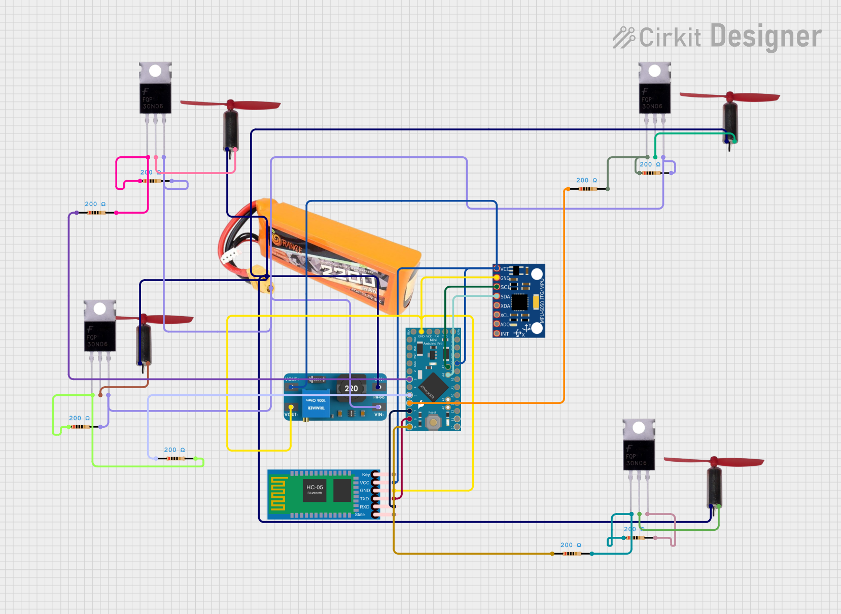

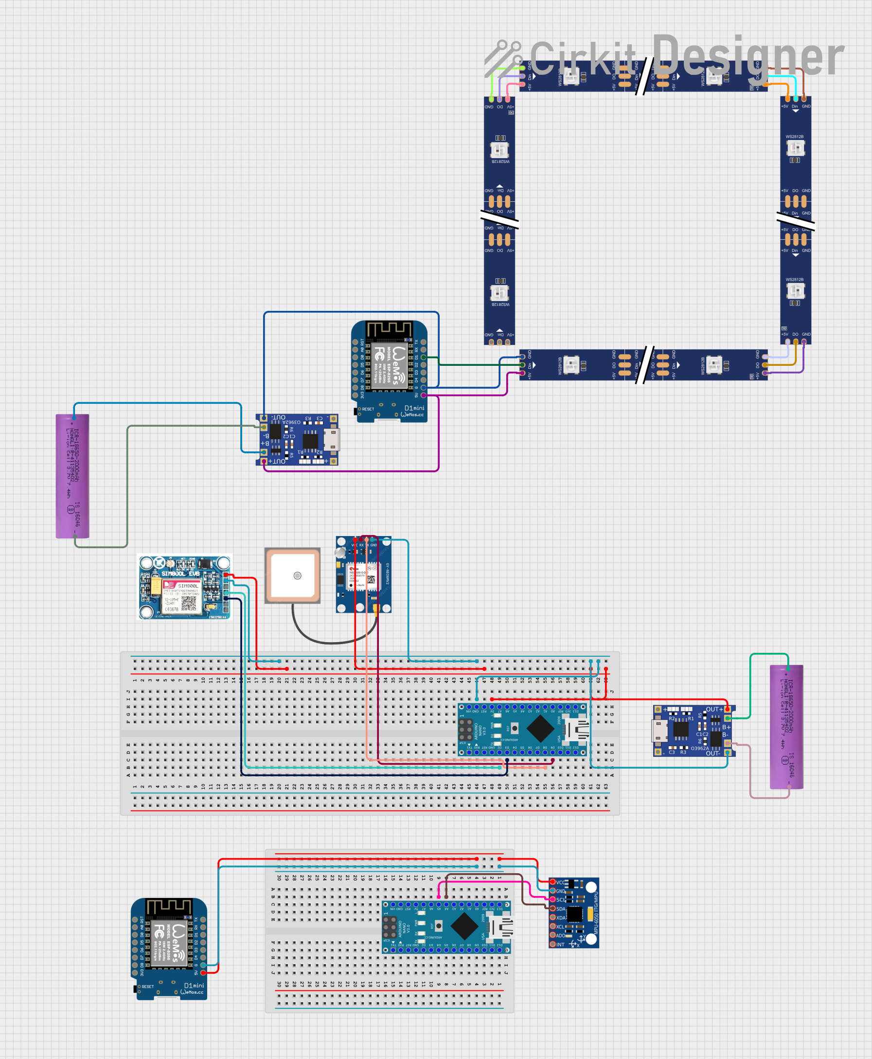

Explore Projects Built with MINI560
Common Applications and Use Cases
- Internet of Things (IoT) devices
- Home automation systems
- Robotics and motor control
- Wearable technology
- Portable data acquisition systems
- Low-power sensor nodes
Technical Specifications
The MINI560 microcontroller is designed to deliver high performance while maintaining energy efficiency. Below are its key technical details:
Key Technical Details
| Parameter | Specification |
|---|---|
| Core Architecture | ARM Cortex-M0+ |
| Operating Voltage | 1.8V to 3.6V |
| Clock Speed | Up to 48 MHz |
| Flash Memory | 64 KB |
| SRAM | 8 KB |
| GPIO Pins | 20 |
| Communication Interfaces | I2C, SPI, UART |
| ADC Resolution | 12-bit, up to 8 channels |
| Timers | 3 (16-bit) |
| Power Consumption | 5 µA in sleep mode, 2 mA active mode |
| Package Type | QFN-32 |
Pin Configuration and Descriptions
The MINI560 comes in a QFN-32 package with the following pin configuration:
| Pin Number | Pin Name | Description |
|---|---|---|
| 1 | VDD | Power supply (1.8V to 3.6V) |
| 2 | GND | Ground |
| 3 | PA0 | GPIO/ADC Channel 0 |
| 4 | PA1 | GPIO/ADC Channel 1 |
| 5 | PA2 | GPIO/UART TX |
| 6 | PA3 | GPIO/UART RX |
| 7 | PA4 | GPIO/SPI CS |
| 8 | PA5 | GPIO/SPI SCK |
| 9 | PA6 | GPIO/SPI MISO |
| 10 | PA7 | GPIO/SPI MOSI |
| 11 | PB0 | GPIO/I2C SDA |
| 12 | PB1 | GPIO/I2C SCL |
| 13 | PB2 | GPIO/ADC Channel 2 |
| 14 | PB3 | GPIO/ADC Channel 3 |
| 15 | PB4 | GPIO/Timer PWM Output |
| 16 | PB5 | GPIO/Timer Input Capture |
| 17-32 | Reserved | Reserved for future use or NC (No Connect) |
Usage Instructions
The MINI560 is versatile and can be used in a variety of embedded applications. Below are the steps and best practices for using the component in a circuit.
How to Use the MINI560 in a Circuit
- Power Supply: Connect the VDD pin to a stable power source (1.8V to 3.6V) and the GND pin to ground.
- GPIO Configuration: Configure the GPIO pins as input or output based on your application. Use pull-up or pull-down resistors if necessary.
- Peripheral Interfaces:
- Use the I2C pins (PB0, PB1) for communication with sensors or other devices.
- Use the SPI pins (PA4-PA7) for high-speed data transfer.
- Use the UART pins (PA2, PA3) for serial communication.
- ADC Usage: Connect analog sensors to the ADC pins (PA0, PA1, PB2, PB3) for data acquisition. Ensure the input voltage does not exceed the reference voltage.
- Timers: Use the timer pins (PB4, PB5) for PWM generation or input capture.
Important Considerations and Best Practices
- Decoupling Capacitors: Place a 0.1 µF ceramic capacitor close to the VDD pin to reduce noise and stabilize the power supply.
- Clock Configuration: Configure the internal or external clock source for optimal performance.
- Low Power Modes: Utilize the sleep mode to reduce power consumption in battery-powered applications.
- Programming: Use an SWD (Serial Wire Debug) interface for programming and debugging the microcontroller.
Example: Connecting the MINI560 to an Arduino UNO
The MINI560 can be interfaced with an Arduino UNO for extended functionality. Below is an example of using the MINI560 as an I2C slave device.
Arduino Code Example
#include <Wire.h> // Include the Wire library for I2C communication

#define MINI560_I2C_ADDRESS 0x42 // Define the I2C address of the MINI560

void setup() {
  Wire.begin(); // Initialize I2C communication as master
  Serial.begin(9600); // Start serial communication for debugging
}

void loop() {
  Wire.beginTransmission(MINI560_I2C_ADDRESS); // Start communication with MINI560
  Wire.write(0x01); // Send a command or data to the MINI560
  Wire.endTransmission(); // End the transmission

  delay(1000); // Wait for 1 second before the next communication
}
Troubleshooting and FAQs
Common Issues and Solutions
Issue: The MINI560 does not power on.
- Solution: Check the power supply voltage and ensure it is within the 1.8V to 3.6V range. Verify the connections to the VDD and GND pins.
Issue: GPIO pins are not functioning as expected.
- Solution: Ensure the pins are correctly configured as input or output in the firmware. Check for any short circuits or incorrect wiring.
Issue: I2C communication is not working.
- Solution: Verify the I2C address of the MINI560 and ensure pull-up resistors (4.7 kΩ) are connected to the SDA and SCL lines.
Issue: ADC readings are inaccurate.
- Solution: Ensure the input voltage to the ADC pins does not exceed the reference voltage. Use proper grounding and shielding to minimize noise.
FAQs
Q: Can the MINI560 operate at 5V?
- A: No, the MINI560 operates within a voltage range of 1.8V to 3.6V. Exceeding this range may damage the component.
Q: How do I program the MINI560?
- A: The MINI560 can be programmed using an SWD interface and compatible programming tools such as ST-Link or J-Link.
Q: Does the MINI560 support external interrupts?
- A: Yes, the MINI560 supports external interrupts on configurable GPIO pins.
Q: Can I use the MINI560 for battery-powered applications?
- A: Yes, the MINI560 is designed for low-power operation, making it suitable for battery-powered devices. Use sleep mode to further reduce power consumption.