How to Use MAIN SWITCH: Examples, Pinouts, and Specs
Introduction
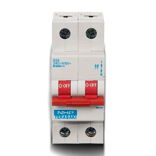
The NHP DIN-T Main Switch 2Pole 80A is a robust and reliable device designed to control the flow of electrical current in a circuit. It serves as a critical component in electrical systems, allowing users to safely open or close circuits as needed. This main switch is particularly suited for industrial, commercial, and residential applications where high current handling and safety are paramount.
Explore Projects Built with MAIN SWITCH


Explore Projects Built with MAIN SWITCH
Common Applications and Use Cases
- Industrial Control Panels: Used to isolate power during maintenance or emergencies.
- Commercial Buildings: Acts as the primary disconnect switch for electrical systems.
- Residential Applications: Provides a safe way to cut off power to specific circuits or the entire home.
- Renewable Energy Systems: Used in solar or wind installations to isolate power sources.
- Motor Control Centers: Ensures safe operation and maintenance of motors.
Technical Specifications
The following table outlines the key technical details of the NHP DIN-T Main Switch 2Pole 80A:
| Specification | Details |
|---|---|
| Manufacturer | NHP |
| Part ID | DIN-T Main Switch 2Pole 80A |
| Number of Poles | 2 |
| Rated Current | 80A |
| Rated Voltage | 415V AC |
| Mounting Type | DIN Rail |
| Operating Temperature | -25°C to +55°C |
| IP Rating | IP20 |
| Mechanical Endurance | 10,000 operations |
| Electrical Endurance | 1,500 operations at full load |
| Compliance Standards | IEC 60947-3, AS/NZS 3947.3 |
Pin Configuration and Descriptions
The NHP DIN-T Main Switch 2Pole 80A has the following terminal configuration:
| Terminal | Description |
|---|---|
| L1 | Line input for the first pole |
| L2 | Line input for the second pole |
| T1 | Load output for the first pole |
| T2 | Load output for the second pole |
| Earth (E) | Optional grounding terminal for safety |
Usage Instructions
How to Use the Component in a Circuit
- Mounting: Securely mount the main switch onto a DIN rail in the desired enclosure or panel.
- Wiring:
- Connect the incoming power lines to the L1 and L2 terminals.
- Connect the outgoing load lines to the T1 and T2 terminals.
- If required, connect the grounding wire to the Earth (E) terminal.
- Operation:
- To close the circuit, move the switch handle to the "ON" position.
- To open the circuit, move the switch handle to the "OFF" position.
- Testing: Verify the connections and ensure the switch operates smoothly before applying full load.
Important Considerations and Best Practices
- Safety First: Always disconnect power before installing or servicing the switch.
- Load Ratings: Ensure the connected load does not exceed the rated current (80A) or voltage (415V AC).
- Proper Grounding: Use the grounding terminal to enhance safety and reduce the risk of electrical shock.
- Environmental Conditions: Avoid installing the switch in areas with excessive moisture, dust, or extreme temperatures.
- Periodic Maintenance: Inspect the switch periodically for signs of wear or damage, and replace it if necessary.
Arduino Integration
While the NHP DIN-T Main Switch 2Pole 80A is not directly compatible with Arduino due to its high current and voltage ratings, it can be used in conjunction with relays or contactors controlled by an Arduino. Below is an example of how to use an Arduino to control a relay that operates the main switch:
// Example code to control a relay for the main switch using Arduino
const int relayPin = 7; // Pin connected to the relay module

void setup() {
  pinMode(relayPin, OUTPUT); // Set the relay pin as an output
  digitalWrite(relayPin, LOW); // Ensure the relay is off initially
}

void loop() {
  // Turn the relay on to close the main switch
  digitalWrite(relayPin, HIGH);
  delay(5000); // Keep the switch on for 5 seconds

  // Turn the relay off to open the main switch
  digitalWrite(relayPin, LOW);
  delay(5000); // Keep the switch off for 5 seconds
}
Note: Ensure the relay module is rated for the voltage and current of the main switch. Use proper isolation techniques to protect the Arduino from high voltages.
Troubleshooting and FAQs
Common Issues Users Might Face
Switch Does Not Operate Smoothly:
- Cause: Mechanical wear or debris in the mechanism.
- Solution: Clean the switch and check for obstructions. Replace if necessary.
Overheating of Terminals:
- Cause: Loose connections or excessive current.
- Solution: Tighten all terminal screws and ensure the load does not exceed 80A.
Switch Fails to Isolate Power:
- Cause: Internal contact failure.
- Solution: Replace the switch immediately to ensure safety.
Arcing During Operation:
- Cause: High inductive loads or damaged contacts.
- Solution: Use an appropriate arc suppression device or replace the switch.
Solutions and Tips for Troubleshooting
- Verify Connections: Double-check all wiring to ensure proper installation.
- Inspect Load: Ensure the connected load is within the switch's rated capacity.
- Test the Switch: Use a multimeter to check continuity when the switch is in the "ON" position.
- Consult the Manufacturer: For persistent issues, refer to NHP's technical support or documentation.
By following this guide, users can safely and effectively utilize the NHP DIN-T Main Switch 2Pole 80A in their electrical systems.