How to Use BH1750FVI: Examples, Pinouts, and Specs
Introduction
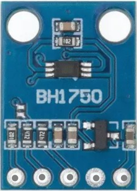
The BH1750FVI is a digital light sensor manufactured by CHINO. It is designed to measure ambient light levels with high accuracy and low power consumption. The sensor communicates via the I2C interface, making it easy to integrate into a wide range of electronic projects and devices. Its compact design and precise measurements make it ideal for applications such as:
- Automatic brightness adjustment in smartphones and tablets
- Smart home lighting systems
- Industrial light monitoring
- Wearable devices
- IoT applications requiring light sensing
Explore Projects Built with BH1750FVI
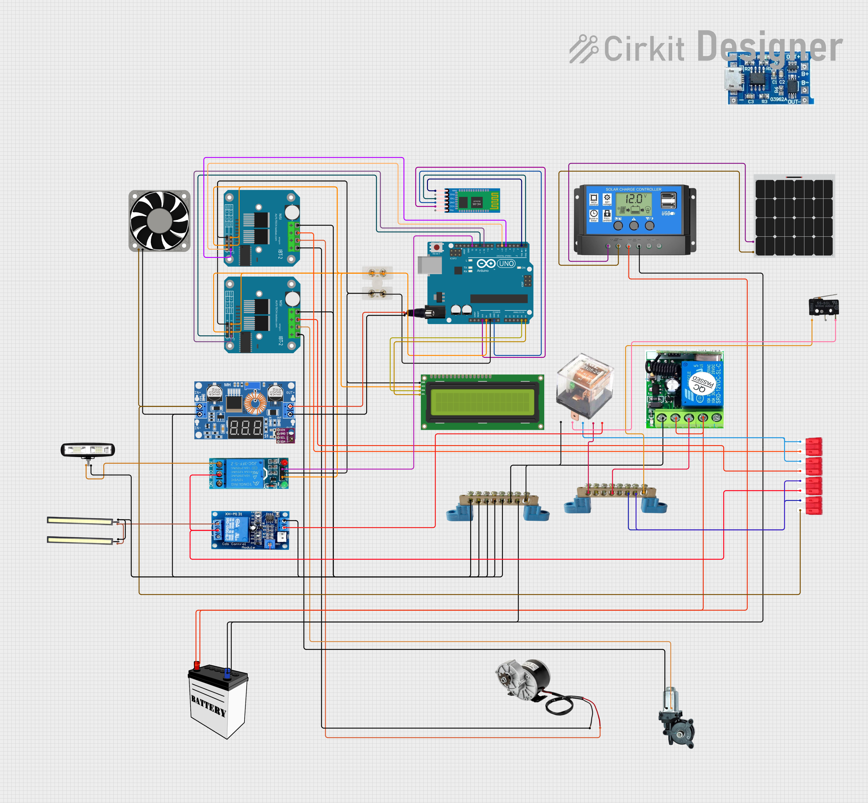
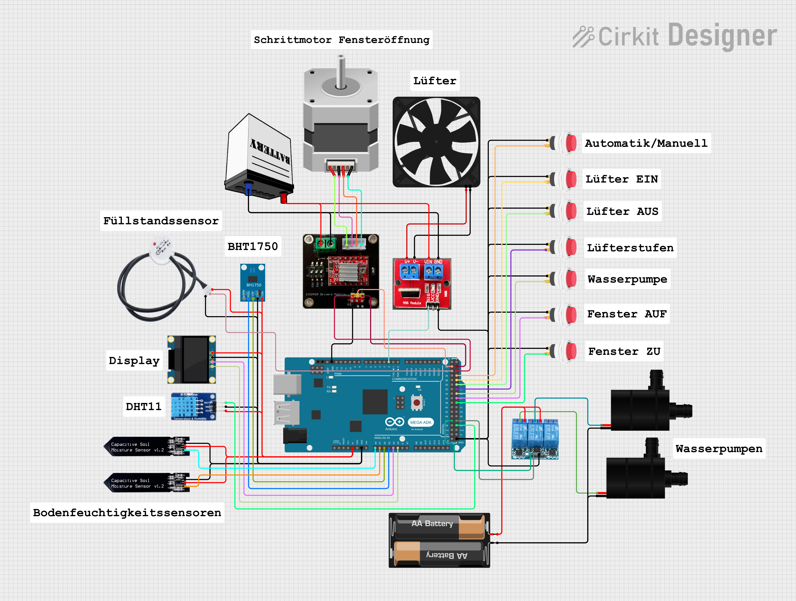
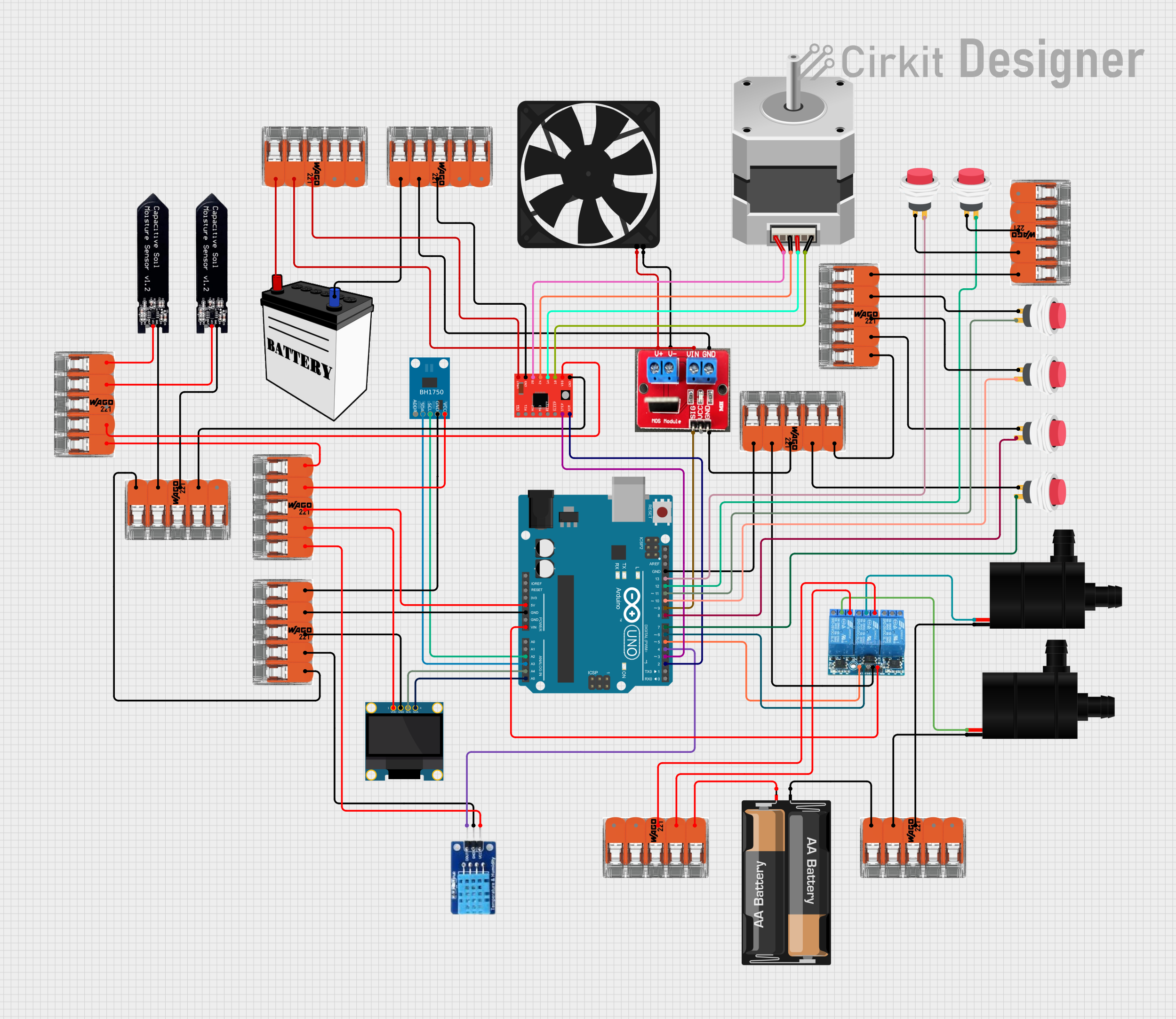
Explore Projects Built with BH1750FVI
Technical Specifications
The following table outlines the key technical details of the BH1750FVI:
| Parameter | Value |
|---|---|
| Operating Voltage (Vcc) | 2.4V to 3.6V |
| Operating Current | 0.12 mA (typical) |
| Measurement Range | 1 lux to 65535 lux |
| Communication Interface | I2C (7-bit address: 0x23 or 0x5C) |
| Light Resolution | 1 lux |
| Operating Temperature | -40°C to +85°C |
| Power Down Current | 0.01 µA (typical) |
Pin Configuration and Descriptions
The BH1750FVI has six pins, as described in the table below:
| Pin Name | Pin Number | Description |
|---|---|---|
| VCC | 1 | Power supply (2.4V to 3.6V) |
| GND | 2 | Ground |
| SDA | 3 | Serial Data Line for I2C communication |
| SCL | 4 | Serial Clock Line for I2C communication |
| ADDR | 5 | I2C address selection (Low: 0x23, High: 0x5C) |
| NC | 6 | Not connected (leave floating or grounded) |
Usage Instructions
How to Use the BH1750FVI in a Circuit
- Power Supply: Connect the VCC pin to a 3.3V power source and the GND pin to ground.
- I2C Communication: Connect the SDA and SCL pins to the corresponding I2C pins on your microcontroller (e.g., Arduino UNO).
- I2C Address Selection: Use the ADDR pin to select the I2C address:
- Connect ADDR to GND for address
0x23. - Connect ADDR to VCC for address
0x5C.
- Connect ADDR to GND for address
- Pull-Up Resistors: Add 4.7kΩ pull-up resistors to the SDA and SCL lines if not already present on your microcontroller board.
- Initialization: Initialize the sensor in your code by sending the appropriate commands over I2C.
Important Considerations and Best Practices
- Avoid exposing the sensor to direct sunlight for extended periods, as it may affect accuracy.
- Place the sensor in a location where it can measure ambient light without obstructions.
- Use decoupling capacitors (e.g., 0.1 µF) near the VCC pin to reduce noise.
- Ensure proper I2C bus termination with pull-up resistors.
Example Code for Arduino UNO
Below is an example of how to use the BH1750FVI with an Arduino UNO:
#include <Wire.h>
#include <BH1750.h>

// Create an instance of the BH1750 library
BH1750 lightMeter;

void setup() {
  Serial.begin(9600); // Initialize serial communication at 9600 baud
  Wire.begin();       // Initialize I2C communication

  // Initialize the BH1750 sensor in continuous high-resolution mode
  if (lightMeter.begin(BH1750::CONTINUOUS_HIGH_RES_MODE)) {
    Serial.println("BH1750 initialized successfully");
  } else {
    Serial.println("Error initializing BH1750");
    while (1); // Halt execution if initialization fails
  }
}

void loop() {
  // Read light level in lux
  float lux = lightMeter.readLightLevel();

  // Print the light level to the serial monitor
  Serial.print("Light Level: ");
  Serial.print(lux);
  Serial.println(" lux");

  delay(1000); // Wait for 1 second before the next reading
}
Notes:
- Install the BH1750 library from the Arduino Library Manager before running the code.
- Ensure the I2C address in the library matches the hardware configuration (default:
0x23).
Troubleshooting and FAQs
Common Issues
No Response from the Sensor
- Cause: Incorrect I2C wiring or address mismatch.
- Solution: Verify the SDA and SCL connections and ensure the ADDR pin is configured correctly.
Inaccurate Light Measurements
- Cause: Sensor placement or environmental factors (e.g., direct sunlight).
- Solution: Reposition the sensor to avoid obstructions or direct light exposure.
Arduino Freezes During Operation
- Cause: I2C communication issues or missing pull-up resistors.
- Solution: Check the I2C bus for proper pull-up resistors and ensure stable connections.
FAQs
Q1: Can the BH1750FVI operate at 5V?
A1: No, the BH1750FVI operates at a voltage range of 2.4V to 3.6V. Use a level shifter if interfacing with a 5V system.
Q2: How do I change the measurement mode?
A2: The BH1750FVI supports multiple modes (e.g., high-resolution, low-resolution). Use the appropriate commands in your code to switch modes.
Q3: What is the maximum I2C clock speed supported?
A3: The BH1750FVI supports I2C clock speeds up to 400 kHz (Fast Mode).
By following this documentation, you can effectively integrate the BH1750FVI into your projects and achieve accurate ambient light measurements.