Cirkit Designer Logo
Cirkit Designer
Your all-in-one circuit design IDE
Home / 
Component Documentation

How to Use raspberry pi: Examples, Pinouts, and Specs
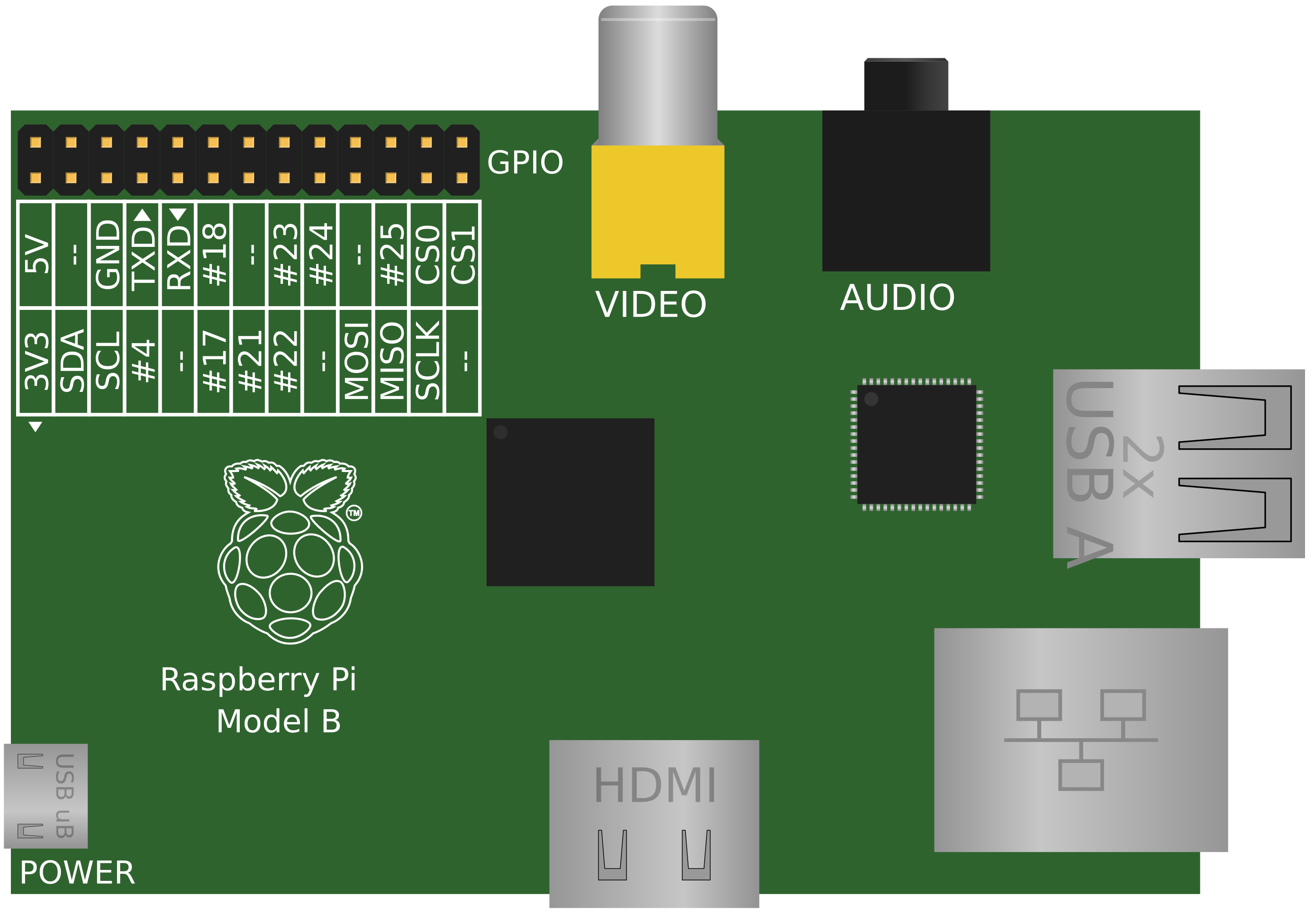

Image of raspberry pi
Cirkit Designer LogoDesign with raspberry pi in Cirkit Designer

Introduction

  • The Raspberry Pi is a small, affordable single-board computer designed for educational, hobbyist, and professional use. It is capable of running a full operating system, such as Linux, and supports a wide range of programming languages and software tools.
  • Common applications include programming education, robotics, Internet of Things (IoT) projects, media centers, home automation, and even lightweight server applications.

Explore Projects Built with raspberry pi
Use Cirkit Designer to design, explore, and prototype these projects online. Some projects support real-time simulation. Click "Open Project" to start designing instantly!
Raspberry Pi 5 Smart Weather Station with GPS and AI Integration
Image of Senior Design: A project utilizing raspberry pi in a practical application
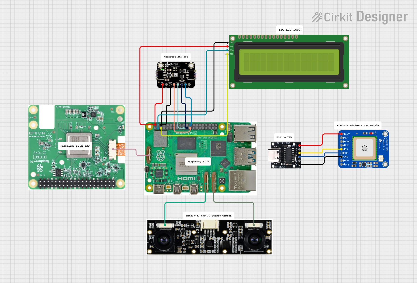
This circuit integrates a Raspberry Pi 5 with various peripherals including an 8MP 3D stereo camera, an AI Hat, a BMP388 sensor, a 16x2 I2C LCD, and an Adafruit Ultimate GPS module. The Raspberry Pi serves as the central processing unit, interfacing with the camera for image capture, the AI Hat for AI processing, the BMP388 for environmental sensing, the LCD for display, and the GPS module for location tracking, with a USB Serial TTL for serial communication.
Cirkit Designer LogoOpen Project in Cirkit Designer
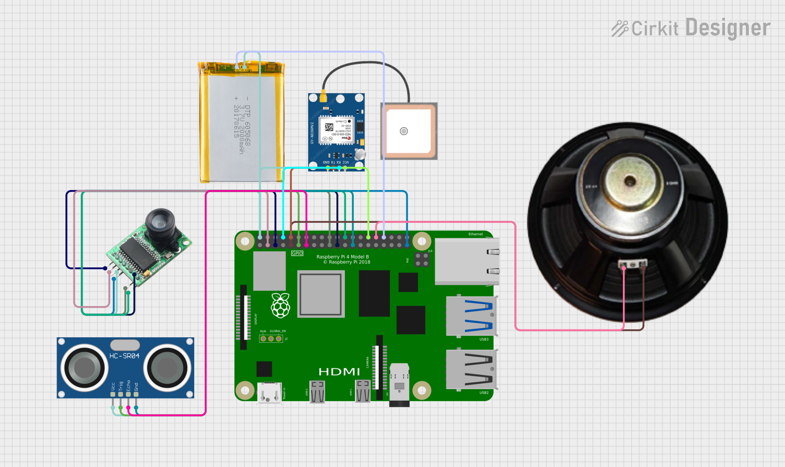
Raspberry Pi 4B-Based Smart Surveillance System with GPS and Ultrasonic Sensing
Image of VisionTool: A project utilizing raspberry pi in a practical application
This circuit features a Raspberry Pi 4B as the central processing unit, interfacing with an Arducam camera module, an HC-SR04 ultrasonic sensor, a GPS NEO 6M module, and a speaker. The Raspberry Pi manages image capture, distance measurement, GPS data reception, and audio output. Power is supplied to the components from a 2000mAh battery, and the Raspberry Pi facilitates communication and control over the I2C, GPIO, and serial interfaces.
Cirkit Designer LogoOpen Project in Cirkit Designer
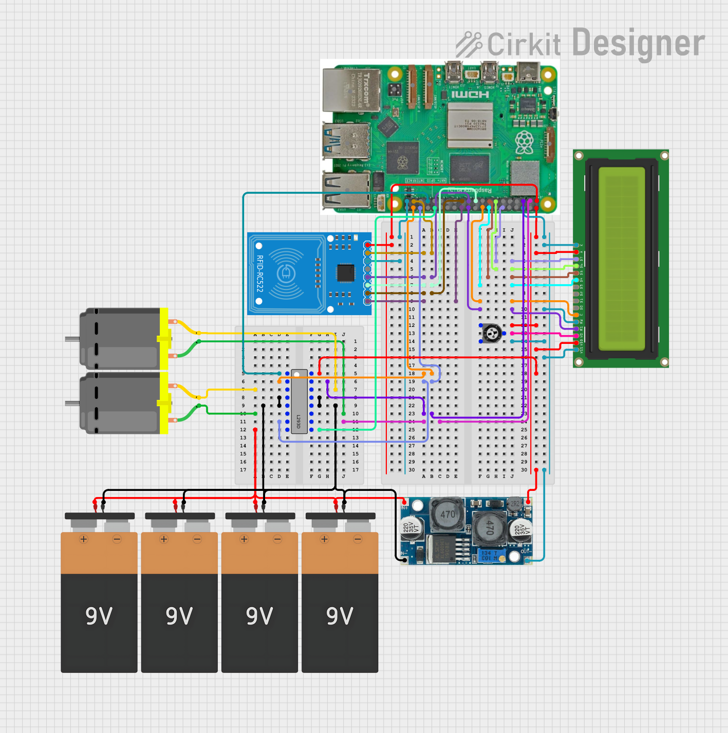
Raspberry Pi 5 RFID Access Control System with LCD Feedback and Dual Motor Control
Image of SpeedyPiMVP: A project utilizing raspberry pi in a practical application
This circuit features a Raspberry Pi 5 as the central controller, interfaced with an RFID-RC522 module for RFID reading capabilities and a 16x2 LCD display for output visualization. The Raspberry Pi controls two DC motors via an L293D motor driver, with speed or direction potentially adjusted by a trimmer potentiometer. Power regulation is managed by an XL6009 voltage regulator, and multiple 9V batteries are used to supply power to the system.
Cirkit Designer LogoOpen Project in Cirkit Designer
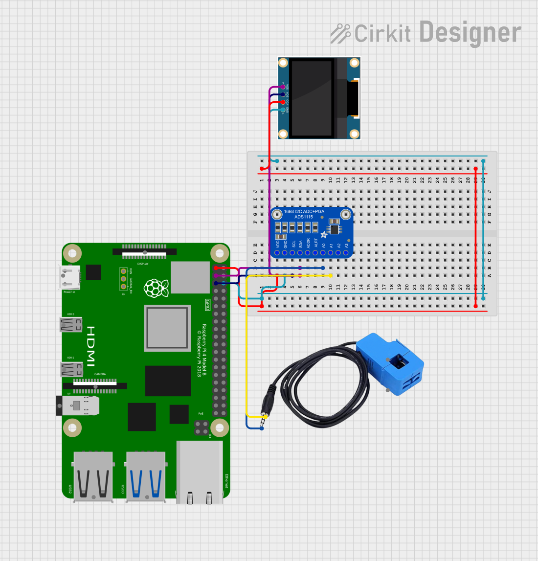
Raspberry Pi 4B-Based Current Monitoring System with I2C OLED Display
Image of Virtual Energy Monitoring Circuit: A project utilizing raspberry pi in a practical application
This circuit features a Raspberry Pi 4B as the central processing unit, interfaced with an Adafruit ADS1115 16-bit I2C ADC for analog-to-digital conversion and a 0.96" OLED display for visual output. The ADS1115 is connected to a current sensor for measuring electrical current, with the sensor's output and burden pins connected to the ADC's analog input channels. The Raspberry Pi communicates with both the ADC and the OLED display over the I2C bus, using its GPIO2 and GPIO3 pins for data (SDA) and clock (SCL) lines, respectively.
Cirkit Designer LogoOpen Project in Cirkit Designer

Explore Projects Built with raspberry pi

Use Cirkit Designer to design, explore, and prototype these projects online. Some projects support real-time simulation. Click "Open Project" to start designing instantly!
Image of Senior Design: A project utilizing raspberry pi in a practical application
Raspberry Pi 5 Smart Weather Station with GPS and AI Integration
This circuit integrates a Raspberry Pi 5 with various peripherals including an 8MP 3D stereo camera, an AI Hat, a BMP388 sensor, a 16x2 I2C LCD, and an Adafruit Ultimate GPS module. The Raspberry Pi serves as the central processing unit, interfacing with the camera for image capture, the AI Hat for AI processing, the BMP388 for environmental sensing, the LCD for display, and the GPS module for location tracking, with a USB Serial TTL for serial communication.
Cirkit Designer LogoOpen Project in Cirkit Designer
Image of VisionTool: A project utilizing raspberry pi in a practical application
Raspberry Pi 4B-Based Smart Surveillance System with GPS and Ultrasonic Sensing
This circuit features a Raspberry Pi 4B as the central processing unit, interfacing with an Arducam camera module, an HC-SR04 ultrasonic sensor, a GPS NEO 6M module, and a speaker. The Raspberry Pi manages image capture, distance measurement, GPS data reception, and audio output. Power is supplied to the components from a 2000mAh battery, and the Raspberry Pi facilitates communication and control over the I2C, GPIO, and serial interfaces.
Cirkit Designer LogoOpen Project in Cirkit Designer
Image of SpeedyPiMVP: A project utilizing raspberry pi in a practical application
Raspberry Pi 5 RFID Access Control System with LCD Feedback and Dual Motor Control
This circuit features a Raspberry Pi 5 as the central controller, interfaced with an RFID-RC522 module for RFID reading capabilities and a 16x2 LCD display for output visualization. The Raspberry Pi controls two DC motors via an L293D motor driver, with speed or direction potentially adjusted by a trimmer potentiometer. Power regulation is managed by an XL6009 voltage regulator, and multiple 9V batteries are used to supply power to the system.
Cirkit Designer LogoOpen Project in Cirkit Designer
Image of Virtual Energy Monitoring Circuit: A project utilizing raspberry pi in a practical application
Raspberry Pi 4B-Based Current Monitoring System with I2C OLED Display
This circuit features a Raspberry Pi 4B as the central processing unit, interfaced with an Adafruit ADS1115 16-bit I2C ADC for analog-to-digital conversion and a 0.96" OLED display for visual output. The ADS1115 is connected to a current sensor for measuring electrical current, with the sensor's output and burden pins connected to the ADC's analog input channels. The Raspberry Pi communicates with both the ADC and the OLED display over the I2C bus, using its GPIO2 and GPIO3 pins for data (SDA) and clock (SCL) lines, respectively.
Cirkit Designer LogoOpen Project in Cirkit Designer

Technical Specifications

The Raspberry Pi comes in various models, such as the Raspberry Pi 4 Model B, Raspberry Pi 3 Model B+, and Raspberry Pi Zero. Below are the general technical specifications for the Raspberry Pi 4 Model B:

Key Technical Details

Specification Details
Processor Quad-core ARM Cortex-A72 (64-bit) at 1.5 GHz
RAM 2GB, 4GB, or 8GB LPDDR4
Storage MicroSD card slot for OS and data storage
USB Ports 2x USB 3.0, 2x USB 2.0
HDMI Ports 2x Micro HDMI (supports up to 4K resolution)
Networking Gigabit Ethernet, 802.11ac Wi-Fi, Bluetooth 5.0
GPIO Pins 40-pin header (3.3V logic, includes I2C, SPI, UART, and GPIO support)
Power Supply 5V/3A via USB-C or GPIO header
Dimensions 85.6mm x 56.5mm x 17mm

GPIO Pin Configuration

The Raspberry Pi features a 40-pin GPIO header. Below is a summary of the pin configuration:

Pin Number Pin Name Description
1 3.3V Power 3.3V power supply
2 5V Power 5V power supply
3 GPIO2 (SDA1) I2C Data
4 5V Power 5V power supply
5 GPIO3 (SCL1) I2C Clock
6 Ground Ground
7 GPIO4 General-purpose I/O
8 GPIO14 (TXD) UART Transmit
9 Ground Ground
10 GPIO15 (RXD) UART Receive
... ... ...
39 Ground Ground
40 GPIO21 General-purpose I/O

For a complete GPIO pinout, refer to the official Raspberry Pi documentation.

Usage Instructions

How to Use the Raspberry Pi

  1. Prepare the Operating System:
    • Download the Raspberry Pi OS (formerly Raspbian) from the official Raspberry Pi website.
    • Flash the OS image onto a microSD card using tools like Balena Etcher or Raspberry Pi Imager.
  2. Set Up the Hardware:
    • Insert the microSD card into the Raspberry Pi.
    • Connect peripherals such as a keyboard, mouse, and monitor.
    • Power the Raspberry Pi using a 5V/3A USB-C power supply.
  3. Boot and Configure:
    • On first boot, follow the on-screen setup wizard to configure Wi-Fi, language, and other settings.
    • Update the system using the terminal command: sudo apt update && sudo apt upgrade.
  4. Programming and Projects:
    • Use Python, Scratch, or other programming languages to create projects.
    • Access GPIO pins using libraries like RPi.GPIO or gpiozero.

Example: Blinking an LED with GPIO

Below is an example of how to blink an LED connected to GPIO pin 17 using Python:


Import necessary libraries

import RPi.GPIO as GPIO import time

Set up GPIO mode and pin

GPIO.setmode(GPIO.BCM) # Use Broadcom pin numbering GPIO.setup(17, GPIO.OUT) # Set GPIO pin 17 as an output

try: while True: GPIO.output(17, GPIO.HIGH) # Turn LED on time.sleep(1) # Wait for 1 second GPIO.output(17, GPIO.LOW) # Turn LED off time.sleep(1) # Wait for 1 second except KeyboardInterrupt: # Clean up GPIO settings on exit GPIO.cleanup()


Important Considerations

  • Always use a proper power supply to avoid undervoltage issues.
  • Be cautious when connecting external components to GPIO pins to prevent damage.
  • Use resistors when connecting LEDs to limit current and protect the GPIO pins.

Troubleshooting and FAQs

Common Issues

  1. Raspberry Pi Does Not Boot:
    • Ensure the microSD card is properly inserted and contains a valid OS image.
    • Check the power supply for sufficient voltage and current.
  2. No Display Output:
    • Verify the HDMI cable and monitor are functioning correctly.
    • Ensure the correct HDMI port is being used (for Raspberry Pi 4, use HDMI0).
  3. Wi-Fi Connectivity Problems:
    • Check the Wi-Fi credentials and signal strength.
    • Update the system firmware using sudo rpi-update.

FAQs

  • Can I power the Raspberry Pi via GPIO pins? Yes, you can supply 5V to the 5V and GND pins, but ensure the power source is stable.

  • How do I enable SSH for remote access? Place an empty file named ssh (no extension) in the boot partition of the microSD card before the first boot.

  • What is the maximum current the GPIO pins can handle? Each GPIO pin can source/sink up to 16mA, with a total maximum of 50mA across all pins.

By following this documentation, you can effectively use the Raspberry Pi for a wide range of projects and applications.