
How to Use Connection Node 1pin: Examples, Pinouts, and Specs
 Design with Connection Node 1pin in Cirkit Designer
Introduction
The Connection Node 1pin is a simple yet versatile electronic component designed to establish a single-point electrical connection in a circuit. It serves as a fundamental building block for integrating various components, enabling seamless connectivity in both prototyping and permanent circuit designs. Its compact design and ease of use make it an essential component for hobbyists, engineers, and educators alike.
Explore Projects Built with Connection Node 1pin
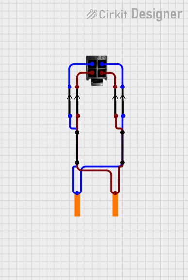 Open Project in Cirkit Designer
 Open Project in Cirkit Designer
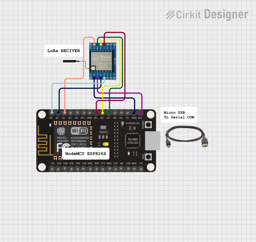 Open Project in Cirkit Designer
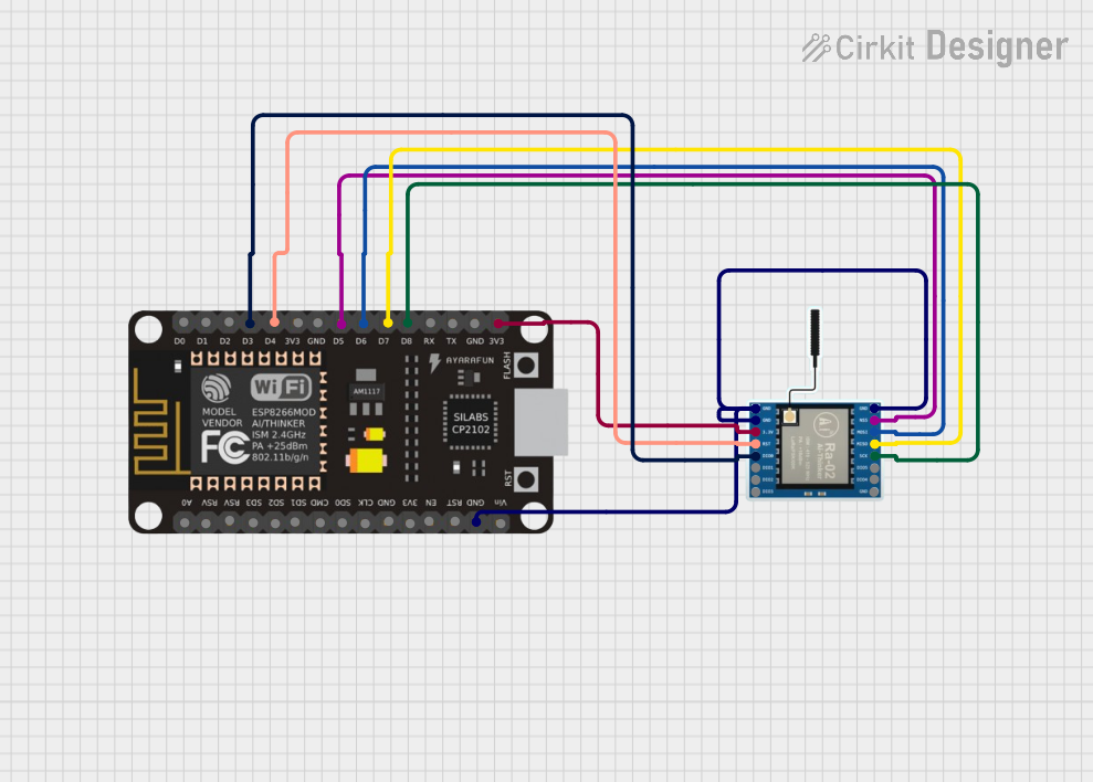 Open Project in Cirkit Designer
Explore Projects Built with Connection Node 1pin
Open Project in Cirkit DesignerOpen Project in Cirkit DesignerOpen Project in Cirkit DesignerOpen Project in Cirkit DesignerCommon Applications and Use Cases
- Prototyping circuits on breadboards or perfboards
- Establishing single-point connections in PCB designs
- Connecting sensors, modules, or other components to microcontrollers
- Creating test points for debugging and measurement
- Extending or branching electrical connections in a circuit
Technical Specifications
The Connection Node 1pin is a passive component with no active electrical properties. Below are its general specifications:
| Parameter | Value |
|---|---|
| Material | Copper (conductive pin), plastic (insulator) |
| Pin Diameter | 0.64 mm (standard) |
| Maximum Current Rating | 3 A |
| Maximum Voltage Rating | 50 V |
| Operating Temperature | -40°C to 85°C |
| Mounting Type | Through-hole or solderable |
Pin Configuration and Descriptions
The Connection Node 1pin has a single pin for electrical connection. Below is the pin description:
| Pin Number | Name | Description |
|---|---|---|
| 1 | Connection Pin | Used to establish an electrical connection point. |
Usage Instructions
How to Use the Component in a Circuit
Breadboard Usage:
- Insert the Connection Node 1pin into a breadboard hole to create a single connection point.
- Connect wires or component leads to the same row on the breadboard to establish an electrical connection.
PCB Usage:
- Solder the Connection Node 1pin into a through-hole on a printed circuit board (PCB).
- Use it as a test point, connection node, or branching point for other components.
Wire Connections:
- Solder a wire directly to the pin for extending connections or integrating with other components.
Important Considerations and Best Practices
- Ensure the current and voltage ratings of the Connection Node 1pin are not exceeded to avoid overheating or damage.
- When soldering, avoid excessive heat to prevent damage to the plastic insulator.
- For reliable connections, ensure the pin is securely inserted into the breadboard or soldered properly onto the PCB.
- Use heat shrink tubing or insulation if the pin is exposed in high-voltage applications to prevent accidental short circuits.
Example: Connecting to an Arduino UNO
The Connection Node 1pin can be used to connect external components, such as sensors or LEDs, to an Arduino UNO. Below is an example of connecting an LED to an Arduino using the Connection Node 1pin:
Circuit Setup
- Insert the Connection Node 1pin into the breadboard.
- Connect one end of a resistor (e.g., 220 ohms) to the Connection Node 1pin.
- Connect the other end of the resistor to the positive leg (anode) of the LED.
- Connect the negative leg (cathode) of the LED to the Arduino's GND pin.
- Use a jumper wire to connect the Connection Node 1pin to a digital pin on the Arduino (e.g., pin 13).
Arduino Code
// Example code to blink an LED connected via Connection Node 1pin
const int ledPin = 13; // Pin connected to the Connection Node 1pin

void setup() {
  pinMode(ledPin, OUTPUT); // Set the pin as an output
}

void loop() {
  digitalWrite(ledPin, HIGH); // Turn the LED on
  delay(1000);               // Wait for 1 second
  digitalWrite(ledPin, LOW);  // Turn the LED off
  delay(1000);               // Wait for 1 second
}
Troubleshooting and FAQs
Common Issues Users Might Face
Loose Connections:
- Problem: The Connection Node 1pin is not making a secure connection in the breadboard or PCB.
- Solution: Ensure the pin is fully inserted into the breadboard or soldered properly onto the PCB.
Overheating:
- Problem: The pin becomes hot during operation.
- Solution: Check that the current and voltage ratings are not being exceeded. Use a thicker wire or additional nodes if necessary.
Corrosion or Oxidation:
- Problem: The pin surface becomes corroded, leading to poor conductivity.
- Solution: Clean the pin with isopropyl alcohol or use a new Connection Node 1pin.
Short Circuits:
- Problem: Exposed pins cause accidental short circuits.
- Solution: Use insulation, such as heat shrink tubing, to cover exposed pins.
FAQs
Q: Can the Connection Node 1pin handle AC signals?
A: Yes, it can handle both AC and DC signals as long as the voltage and current ratings are not exceeded.
Q: Is the Connection Node 1pin reusable?
A: Yes, it can be reused in breadboard applications. However, for soldered connections, desoldering may damage the pin or PCB.
Q: Can I use the Connection Node 1pin for high-frequency signals?
A: While it can be used for high-frequency signals, ensure that the pin's inductance and resistance do not affect the circuit's performance.
Q: What tools are needed to solder the Connection Node 1pin?
A: A soldering iron, solder wire, and optionally, flux and heat shrink tubing for insulation.