How to Use 3RT2016-1BB41 Power Contactor: Examples, Pinouts, and Specs
Introduction
The 3RT2016-1BB41 is a power contactor designed for switching electrical circuits in industrial and automation environments. It is primarily used to control high-power loads such as motors, heaters, and lighting systems. With its compact design and reliable performance, this contactor is ideal for applications requiring frequent switching and high current handling. Its robust construction ensures durability and consistent operation in demanding conditions.
Explore Projects Built with 3RT2016-1BB41 Power Contactor


Explore Projects Built with 3RT2016-1BB41 Power Contactor
Common Applications
- Motor control in industrial automation systems
- Switching of resistive and inductive loads
- HVAC systems and lighting control
- Conveyor systems and material handling equipment
- Power distribution and control panels
Technical Specifications
Key Technical Details
| Parameter | Value |
|---|---|
| Rated Operational Voltage | Up to 690 V AC |
| Rated Operational Current | 16 A |
| Control Voltage | 24 V AC/DC |
| Number of Poles | 3 (Three-phase) |
| Frequency Range | 50/60 Hz |
| Mechanical Durability | 10 million operations |
| Electrical Durability | 1 million operations (at rated load) |
| Mounting Type | DIN rail or screw mounting |
| Operating Temperature Range | -25°C to +60°C |
| Dimensions (H x W x D) | 58 mm x 45 mm x 73 mm |
| Weight | Approximately 0.3 kg |
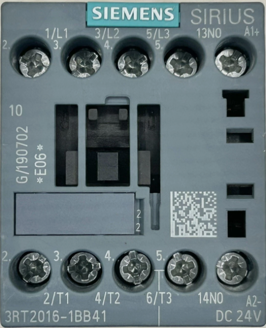
Pin Configuration and Descriptions
The 3RT2016-1BB41 has a straightforward terminal layout for easy integration into circuits. Below is the pin configuration:
Power Terminals
| Terminal | Description |
|---|---|
| L1 | Input for phase 1 (Line 1) |
| L2 | Input for phase 2 (Line 2) |
| L3 | Input for phase 3 (Line 3) |
| T1 | Output for phase 1 (Load 1) |
| T2 | Output for phase 2 (Load 2) |
| T3 | Output for phase 3 (Load 3) |
Control Terminals
| Terminal | Description |
|---|---|
| A1 | Control coil input (positive) |
| A2 | Control coil input (negative) |
Usage Instructions
How to Use the 3RT2016-1BB41 in a Circuit
Power Connections:
- Connect the three-phase power supply to the input terminals (L1, L2, L3).
- Connect the load (e.g., motor, heater) to the output terminals (T1, T2, T3).
Control Circuit:
- Supply the control voltage (24 V AC/DC) to the coil terminals (A1 and A2).
- Use a push-button switch or relay to control the activation of the contactor.
Mounting:
- Secure the contactor to a DIN rail or use screws for panel mounting.
- Ensure proper spacing for ventilation and heat dissipation.
Safety Precautions:
- Always disconnect power before wiring or servicing the contactor.
- Verify that the voltage and current ratings match the application requirements.
- Use appropriate fuses or circuit breakers for overload protection.
Important Considerations and Best Practices
- Ensure the control voltage matches the rated coil voltage (24 V AC/DC).
- Avoid exceeding the rated operational current (16 A) to prevent overheating or damage.
- Use proper cable sizing to handle the load current safely.
- Regularly inspect the contactor for signs of wear or damage, especially in high-duty-cycle applications.
- For inductive loads, consider using surge suppressors to protect the contactor from voltage spikes.
Example: Connecting the 3RT2016-1BB41 to an Arduino UNO
The 3RT2016-1BB41 can be controlled using an Arduino UNO by interfacing the control coil with a relay module. Below is an example code snippet:
// Example code to control the 3RT2016-1BB41 contactor using an Arduino UNO
// and a relay module. The relay module is used to switch the 24 V control
// voltage to the contactor's coil terminals (A1 and A2).

const int relayPin = 7; // Pin connected to the relay module

void setup() {
  pinMode(relayPin, OUTPUT); // Set the relay pin as an output
  digitalWrite(relayPin, LOW); // Ensure the relay is off initially
}

void loop() {
  // Turn the contactor ON
  digitalWrite(relayPin, HIGH); // Activate the relay
  delay(5000); // Keep the contactor ON for 5 seconds

  // Turn the contactor OFF
  digitalWrite(relayPin, LOW); // Deactivate the relay
  delay(5000); // Keep the contactor OFF for 5 seconds
}
Note: Ensure the relay module is rated for the control voltage (24 V AC/DC) and can handle the current required by the contactor's coil.
Troubleshooting and FAQs
Common Issues and Solutions
| Issue | Possible Cause | Solution |
|---|---|---|
| Contactor does not activate | No control voltage applied to the coil | Verify the control voltage at A1 and A2. |
| Contactor buzzes or vibrates | Insufficient or unstable control voltage | Check the power supply and connections. |
| Overheating of the contactor | Exceeding the rated operational current | Reduce the load or use a higher-rated contactor. |
| Frequent contactor failure | High inrush current from inductive loads | Use surge suppressors or snubber circuits. |
| Loose or damaged terminals | Improper wiring or mechanical stress | Inspect and tighten all connections. |
FAQs
Can the 3RT2016-1BB41 be used for single-phase loads?
- Yes, it can be used for single-phase loads by connecting only one phase input (L1) and output (T1).
What is the maximum switching frequency?
- The contactor can handle up to 15 switching operations per minute under normal conditions.
Is the contactor suitable for outdoor use?
- The contactor is not designed for direct outdoor use. It should be installed in a weatherproof enclosure if used outdoors.
Can I use a DC power supply for the control coil?
- Yes, the control coil supports both AC and DC voltages at 24 V.
By following this documentation, users can effectively integrate the 3RT2016-1BB41 Power Contactor into their systems and ensure reliable operation.