How to Use CD4026: Examples, Pinouts, and Specs
Introduction
The CD4026 is a decade counter and display driver manufactured by NXP Semiconductors (Part ID: CD4026BNSR). This versatile integrated circuit (IC) is designed to count from 0 to 9 in binary-coded decimal (BCD) format and directly drive a 7-segment display. It simplifies the process of creating digital counters, making it ideal for applications such as digital clocks, frequency counters, and event counters.
Explore Projects Built with CD4026

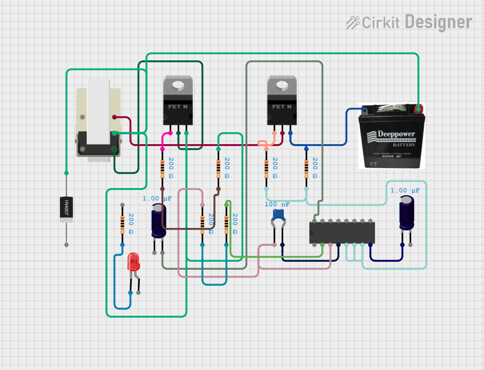

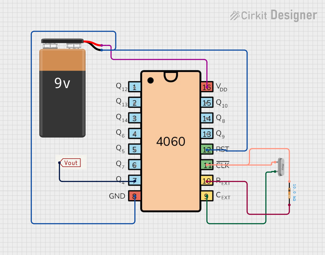
Explore Projects Built with CD4026
Common Applications
- Digital clocks
- Frequency counters
- Event counters
- Scoreboards
- Simple numerical displays
Technical Specifications
Key Technical Details
| Parameter | Value |
|---|---|
| Supply Voltage (V(_{DD})) | 3V to 15V |
| Input Voltage Range | 0V to V(_{DD}) |
| Maximum Clock Frequency | 6 MHz (at V(_{DD}) = 10V) |
| Output Current (per pin) | ±1.5 mA |
| Operating Temperature Range | -55°C to +125°C |
| Package Type | SOIC-16, PDIP-16, TSSOP-16 |
Pin Configuration and Descriptions
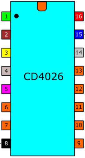
The CD4026 has 16 pins, each serving a specific function. Below is the pinout and description:
| Pin No. | Pin Name | Description |
|---|---|---|
| 1 | Clock (CLK) | Input for clock signal; increments the counter on a rising edge. |
| 2 | Enable (EN) | Enables counting when HIGH; disables counting when LOW. |
| 3 | Clock Inhibit | Disables the clock input when HIGH; allows clock input when LOW. |
| 4 | Display Enable | Enables the 7-segment display output when HIGH. |
| 5 | Segment A | Output for segment A of the 7-segment display. |
| 6 | Segment B | Output for segment B of the 7-segment display. |
| 7 | Segment C | Output for segment C of the 7-segment display. |
| 8 | GND | Ground connection. |
| 9 | Segment D | Output for segment D of the 7-segment display. |
| 10 | Segment E | Output for segment E of the 7-segment display. |
| 11 | Segment F | Output for segment F of the 7-segment display. |
| 12 | Segment G | Output for segment G of the 7-segment display. |
| 13 | Carry Out | Outputs a carry signal for cascading multiple CD4026 ICs. |
| 14 | Not Used | No internal connection; leave unconnected. |
| 15 | Reset | Resets the counter to 0 when HIGH. |
| 16 | V(_{DD}) | Positive supply voltage. |
Usage Instructions
How to Use the CD4026 in a Circuit
- Power Supply: Connect pin 16 (V(_{DD})) to the positive supply voltage (3V to 15V) and pin 8 (GND) to ground.
- Clock Input: Provide a clock signal to pin 1 (CLK). Each rising edge of the clock signal increments the counter.
- Enable Counting: Ensure pin 2 (EN) is HIGH to enable counting. If LOW, the counter will not increment.
- Reset: To reset the counter to 0, momentarily set pin 15 (Reset) HIGH.
- Display Enable: Set pin 4 HIGH to enable the 7-segment display output.
- 7-Segment Display: Connect the segment outputs (pins 5–7, 9–12) to the corresponding segments of a common cathode 7-segment display.
- Cascading: Use pin 13 (Carry Out) to cascade multiple CD4026 ICs for counting beyond 9.
Important Considerations
- Use a current-limiting resistor for each segment of the 7-segment display to prevent damage.
- Ensure the clock signal is clean and free of noise to avoid erratic counting.
- For higher counting ranges, cascade multiple CD4026 ICs using the Carry Out pin.
Example: Connecting CD4026 to an Arduino UNO
Below is an example of how to connect and control the CD4026 with an Arduino UNO to drive a 7-segment display.
Circuit Connections
- Connect the CD4026's CLK pin to Arduino pin 2.
- Connect the Reset pin to Arduino pin 3.
- Connect the Display Enable pin to 5V.
- Connect the segment outputs (A–G) to the corresponding pins of a common cathode 7-segment display.
- Connect the GND pin to ground and V(_{DD}) to 5V.
Arduino Code
// Define pin connections
const int clockPin = 2;  // Clock input to CD4026
const int resetPin = 3;  // Reset input to CD4026

void setup() {
  pinMode(clockPin, OUTPUT);  // Set clock pin as output
  pinMode(resetPin, OUTPUT);  // Set reset pin as output

  // Initialize pins
  digitalWrite(clockPin, LOW);
  digitalWrite(resetPin, LOW);
}

void loop() {
  // Reset the counter
  digitalWrite(resetPin, HIGH);  // Send a HIGH signal to reset
  delay(10);                     // Wait for 10ms
  digitalWrite(resetPin, LOW);   // Set reset back to LOW

  // Increment the counter
  for (int i = 0; i < 10; i++) { // Count from 0 to 9
    digitalWrite(clockPin, HIGH);  // Send a rising edge
    delay(100);                    // Wait for 100ms
    digitalWrite(clockPin, LOW);   // Send a falling edge
    delay(100);                    // Wait for 100ms
  }
}
Troubleshooting and FAQs
Common Issues
The 7-segment display does not light up.
- Ensure the Display Enable pin is HIGH.
- Check the connections between the CD4026 and the 7-segment display.
- Verify that the 7-segment display is a common cathode type.
The counter skips numbers or behaves erratically.
- Ensure the clock signal is clean and free of noise.
- Use a pull-down resistor on the clock input if necessary.
- Verify that the Clock Inhibit pin is LOW.
The counter does not reset.
- Ensure the Reset pin is momentarily set HIGH to reset the counter.
- Check the connection to the Reset pin.
FAQs
Q: Can I use the CD4026 with a common anode 7-segment display?
A: No, the CD4026 is designed to work with common cathode 7-segment displays.
Q: How can I count beyond 9?
A: Use the Carry Out pin to cascade multiple CD4026 ICs. Connect the Carry Out pin of the first IC to the Clock pin of the next IC.
Q: What is the maximum clock frequency for the CD4026?
A: The maximum clock frequency is 6 MHz when operating at a supply voltage of 10V.