How to Use Portenta Machine Control: Examples, Pinouts, and Specs
Introduction
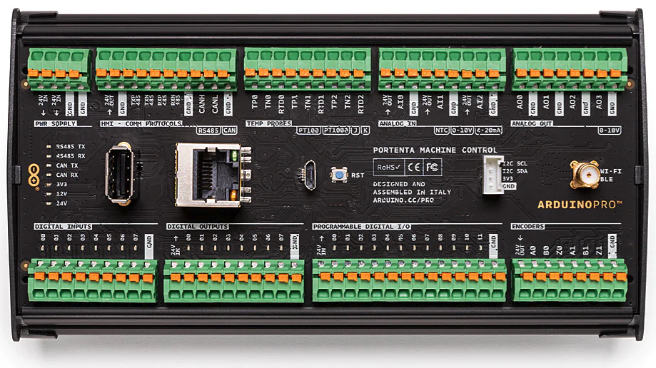
The Portenta Machine Control is a robust and versatile microcontroller board developed by Arduino, specifically designed for industrial applications. It combines advanced connectivity options, real-time processing capabilities, and support for a wide range of sensors and actuators. This makes it an ideal choice for IoT, industrial automation, and edge computing projects.
The Portenta Machine Control is built to operate in demanding environments, offering features such as industrial-grade I/O, compatibility with industrial protocols, and the ability to interface with external devices like motors, relays, and sensors. Its modular design and powerful processing capabilities make it suitable for applications such as predictive maintenance, smart factories, and remote monitoring systems.
Explore Projects Built with Portenta Machine Control


Explore Projects Built with Portenta Machine Control
Common Applications and Use Cases
- Industrial automation and control systems
- IoT-enabled smart factories
- Predictive maintenance and condition monitoring
- Edge computing and real-time data processing
- Remote monitoring and diagnostics
- Integration with PLCs and industrial networks
Technical Specifications
Key Technical Details
| Specification | Details |
|---|---|
| Processor | Dual-core Arm® Cortex®-M7 (480 MHz) and Cortex®-M4 (240 MHz) |
| Memory | 8 MB SDRAM, 16 MB NOR Flash |
| Connectivity | Ethernet, Wi-Fi, Bluetooth® Low Energy (BLE) |
| Operating Voltage | 24V DC (industrial standard) |
| Digital I/O | 17 digital I/O pins (industrial-grade, opto-isolated) |
| Analog Inputs | 8 analog inputs (12-bit resolution) |
| Relay Outputs | 4 relay outputs (2A @ 30V DC or 0.5A @ 125V AC) |
| Communication Protocols | RS485, CAN, I2C, SPI, UART, Modbus, OPC UA |
| Operating Temperature | -40°C to +85°C |
| Dimensions | 170 x 90 x 60 mm |
| Mounting | DIN rail mountable |
Pin Configuration and Descriptions
| Pin Name | Type | Description |
|---|---|---|
| D0 - D16 | Digital I/O | Industrial-grade digital input/output pins, opto-isolated for noise immunity. |
| A0 - A7 | Analog Input | 12-bit resolution analog inputs for sensors and other analog devices. |
| Relay1 - Relay4 | Relay Output | High-power relay outputs for controlling external devices like motors or lights. |
| RS485+ / RS485- | Communication | RS485 differential pair for industrial communication. |
| CANH / CANL | Communication | CAN bus high and low lines for automotive and industrial networks. |
| ETH | Ethernet | RJ45 Ethernet port for wired network connectivity. |
| Wi-Fi / BLE | Wireless | Integrated Wi-Fi and Bluetooth® Low Energy for wireless communication. |
| 24V IN | Power Input | 24V DC power input for industrial power supplies. |
Usage Instructions
How to Use the Component in a Circuit
- Powering the Board: Connect a 24V DC power supply to the
24V INterminal. Ensure the power supply is stable and within the specified voltage range. - Connecting Sensors and Actuators:
- Use the
A0 - A7pins for analog sensors (e.g., temperature, pressure sensors). - Use the
D0 - D16pins for digital sensors or actuators (e.g., switches, LEDs). - For high-power devices, connect them to the
Relay1 - Relay4outputs.
- Use the
- Communication:
- Use the RS485 or CAN bus for industrial communication with other devices.
- For networked applications, connect the Ethernet port or configure the Wi-Fi/BLE module.
- Programming:
- The Portenta Machine Control can be programmed using the Arduino IDE or other compatible environments.
- Connect the board to your computer via USB or over the network for programming and debugging.
Important Considerations and Best Practices
- Power Supply: Always use a regulated 24V DC power supply to avoid damage to the board.
- Isolation: The digital I/O pins are opto-isolated, providing protection against electrical noise. Ensure proper grounding for reliable operation.
- Relay Outputs: Do not exceed the rated current and voltage for the relay outputs to prevent damage.
- Industrial Protocols: When using RS485 or CAN, ensure proper termination resistors are in place for reliable communication.
- Environment: The board is designed for industrial environments but avoid exposure to excessive moisture or corrosive substances.
Example Code for Arduino IDE
The following example demonstrates how to read an analog sensor and control a relay output using the Portenta Machine Control:
// Include necessary libraries
#include <Arduino.h>

// Define pin assignments
#define ANALOG_SENSOR_PIN A0  // Analog sensor connected to A0
#define RELAY_OUTPUT_PIN  2   // Relay output connected to D2

void setup() {
  // Initialize serial communication for debugging
  Serial.begin(9600);

  // Configure pins
  pinMode(ANALOG_SENSOR_PIN, INPUT);  // Set A0 as input
  pinMode(RELAY_OUTPUT_PIN, OUTPUT); // Set D2 as output

  // Initialize relay to OFF state
  digitalWrite(RELAY_OUTPUT_PIN, LOW);
}

void loop() {
  // Read analog sensor value
  int sensorValue = analogRead(ANALOG_SENSOR_PIN);

  // Print sensor value to serial monitor
  Serial.print("Sensor Value: ");
  Serial.println(sensorValue);

  // Control relay based on sensor value
  if (sensorValue > 512) {
    digitalWrite(RELAY_OUTPUT_PIN, HIGH); // Turn relay ON
  } else {
    digitalWrite(RELAY_OUTPUT_PIN, LOW);  // Turn relay OFF
  }

  // Add a small delay for stability
  delay(500);
}
Troubleshooting and FAQs
Common Issues and Solutions
Board Not Powering On:
- Ensure the 24V DC power supply is properly connected and within the specified voltage range.
- Check for loose connections or damaged cables.
No Communication Over RS485 or CAN:
- Verify that the termination resistors are correctly installed.
- Ensure the communication protocol settings (e.g., baud rate) match between devices.
Relay Outputs Not Working:
- Check the connected load to ensure it does not exceed the relay's rated current and voltage.
- Verify that the relay control pins are correctly configured in the code.
Wi-Fi or BLE Not Connecting:
- Ensure the correct SSID and password are used for Wi-Fi connections.
- Check for interference or weak signal strength in the operating environment.
Tips for Troubleshooting
- Use the serial monitor in the Arduino IDE to debug and monitor sensor readings or communication status.
- Test individual components (e.g., sensors, actuators) separately to isolate issues.
- Refer to the official Arduino documentation and community forums for additional support.