How to Use FAN 12V: Examples, Pinouts, and Specs
Introduction
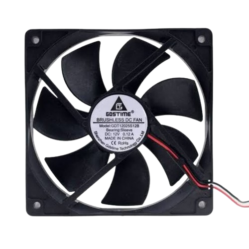
The FAN 12V is a compact and efficient cooling fan designed to operate at a nominal voltage of 12 volts. It is widely used in electronic systems to dissipate heat, ensuring the longevity and optimal performance of components. This fan is commonly found in applications such as computer systems, power supplies, 3D printers, and other devices requiring active airflow for cooling.
Explore Projects Built with FAN 12V


Explore Projects Built with FAN 12V
Common Applications and Use Cases
- Cooling microcontrollers, processors, and power transistors
- Ventilation in enclosures and cabinets
- Heat dissipation in power supplies and battery packs
- Airflow management in 3D printers and robotics
Technical Specifications
The following table outlines the key technical details of the FAN 12V:
| Parameter | Value |
|---|---|
| Operating Voltage | 12V DC |
| Operating Current | 0.1A to 0.3A (typical) |
| Power Consumption | 1.2W to 3.6W |
| Fan Speed | 2000 to 5000 RPM |
| Airflow | 20 to 50 CFM (Cubic Feet per Minute) |
| Noise Level | 20 to 40 dBA |
| Dimensions | 40x40mm, 60x60mm, or 80x80mm (varies by model) |
| Bearing Type | Sleeve or Ball Bearing |
| Connector Type | 2-pin or 3-pin JST |
Pin Configuration and Descriptions
The FAN 12V typically comes with a 2-pin or 3-pin connector. The pinout is as follows:
2-Pin Connector
| Pin Number | Wire Color | Description |
|---|---|---|
| 1 | Red | Positive Voltage (12V) |
| 2 | Black | Ground (GND) |
3-Pin Connector
| Pin Number | Wire Color | Description |
|---|---|---|
| 1 | Red | Positive Voltage (12V) |
| 2 | Black | Ground (GND) |
| 3 | Yellow | Tachometer Signal (optional, for speed monitoring) |
Usage Instructions
How to Use the FAN 12V in a Circuit
- Power Supply: Ensure the fan is connected to a stable 12V DC power source. Exceeding the voltage rating may damage the fan.
- Wiring:
- For a 2-pin fan, connect the red wire to the positive terminal of the power supply and the black wire to the ground.
- For a 3-pin fan, connect the red and black wires as above. The yellow wire can be connected to a microcontroller or monitoring circuit to read the fan's speed.
- Mounting: Secure the fan using screws or adhesive mounts to ensure proper airflow direction. Most fans have an arrow indicating the airflow direction.
Important Considerations and Best Practices
- Airflow Direction: Verify the airflow direction before installation. The fan typically has arrows indicating the airflow and blade rotation direction.
- Noise Reduction: Use rubber mounts or grommets to minimize vibration and noise.
- Speed Control: For variable speed control, use a PWM (Pulse Width Modulation) signal on the power line or a dedicated speed control circuit.
- Heat Management: Ensure the fan is not obstructed by cables or other components to maintain optimal cooling performance.
Example: Connecting FAN 12V to an Arduino UNO
The FAN 12V can be controlled using an Arduino UNO and a transistor for switching. Below is an example circuit and code:
Circuit Diagram
- Connect the red wire of the fan to the collector of an NPN transistor (e.g., 2N2222).
- Connect the black wire of the fan to the ground (GND).
- Connect the emitter of the transistor to GND.
- Connect a 1kΩ resistor between the base of the transistor and a PWM-capable pin on the Arduino (e.g., Pin 9).
- Connect the Arduino's GND to the power supply's GND.
Arduino Code
// FAN 12V control using Arduino UNO
// This code uses PWM to control the fan speed via Pin 9.

const int fanPin = 9; // PWM pin connected to the transistor base

void setup() {
  pinMode(fanPin, OUTPUT); // Set the fan pin as an output
}

void loop() {
  analogWrite(fanPin, 128); // Set fan speed to 50% (128 out of 255)
  delay(5000); // Run at 50% speed for 5 seconds

  analogWrite(fanPin, 255); // Set fan speed to 100% (255 out of 255)
  delay(5000); // Run at full speed for 5 seconds
}
Troubleshooting and FAQs
Common Issues and Solutions
Fan Does Not Spin
- Cause: No power supply or incorrect wiring.
- Solution: Verify the power supply voltage is 12V and check the wiring connections.
Fan Spins Slowly
- Cause: Insufficient power or high resistance in the circuit.
- Solution: Ensure the power supply can provide sufficient current (at least 0.3A).
Excessive Noise
- Cause: Vibration or worn-out bearings.
- Solution: Use rubber mounts to reduce vibration or replace the fan if bearings are damaged.
Fan Overheats
- Cause: Prolonged operation at high speed or blocked airflow.
- Solution: Ensure proper ventilation and avoid running the fan at maximum speed continuously.
FAQs
Q: Can I use the FAN 12V with a 5V power supply?
A: No, the FAN 12V is designed to operate at 12V. Using a lower voltage will result in reduced performance or failure to spin.
Q: How do I monitor the fan speed with the yellow wire?
A: The yellow wire outputs a tachometer signal (pulses per revolution). Connect it to a microcontroller's input pin and use an interrupt or pulse-counting function to measure the speed.
Q: Can I control the fan speed without a microcontroller?
A: Yes, you can use a variable resistor (potentiometer) or a dedicated fan speed controller circuit to adjust the voltage or PWM signal.
Q: Is the FAN 12V waterproof?
A: Most FAN 12V models are not waterproof. Check the manufacturer's specifications for IP-rated fans if water resistance is required.