How to Use DRV2605 Motor Controller: Examples, Pinouts, and Specs
Introduction
The DRV2605 is a haptic motor driver designed to provide precise control of vibration motors, including both Linear Resonant Actuators (LRAs) and Eccentric Rotating Mass (ERM) motors. It features an integrated library of pre-programmed haptic waveforms, making it ideal for creating customizable haptic feedback effects. The device communicates via the I2C interface, enabling seamless integration with microcontrollers and other digital systems.
Explore Projects Built with DRV2605 Motor Controller


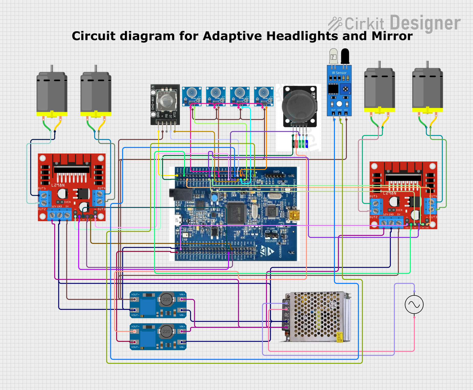
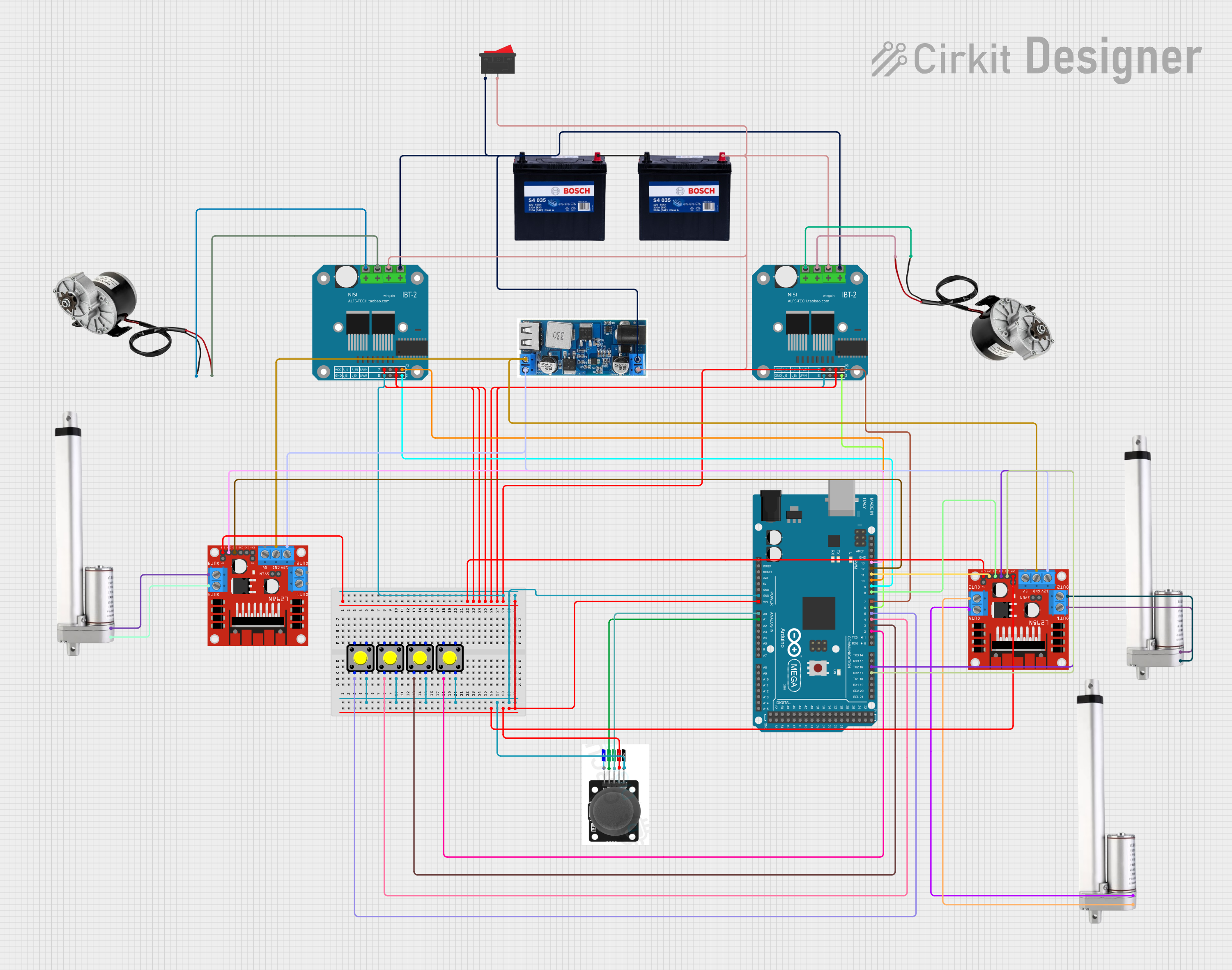
Explore Projects Built with DRV2605 Motor Controller
Common Applications
- Smartphones and tablets for tactile feedback
- Wearable devices such as smartwatches and fitness trackers
- Gaming controllers for immersive haptic effects
- Medical devices requiring precise vibration control
- Automotive touch interfaces
Technical Specifications
The DRV2605 is a versatile and feature-rich motor driver. Below are its key technical details:
Key Features
- Operating Voltage: 2.5V to 5.5V
- Output Drive Voltage: Up to 5.5V
- Motor Types Supported: ERM and LRA
- Communication Interface: I2C (7-bit address)
- Built-in Waveforms: Over 100 pre-programmed haptic effects
- Current Consumption:
- Active mode: ~1.5mA
- Standby mode: ~10µA
- Operating Temperature: -40°C to 85°C
- Package: 10-pin VSON (3mm x 3mm)
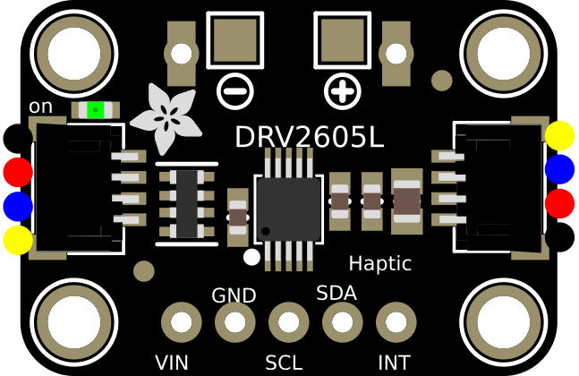
Pin Configuration
The DRV2605 has 10 pins, as described in the table below:
| Pin Name | Type | Description |
|---|---|---|
| VDD | Power | Supply voltage (2.5V to 5.5V). |
| GND | Ground | Ground connection. |
| IN/TRIG | Input | Trigger input for external waveform playback (optional). |
| SDA | I2C Data | Serial data line for I2C communication. |
| SCL | I2C Clock | Serial clock line for I2C communication. |
| EN | Input | Enable pin. Active high to enable the device. |
| OUT+ | Output | Positive output to the motor. |
| OUT- | Output | Negative output to the motor. |
| NC | No Connection | Not connected internally. Leave floating or connect to GND. |
| VREG | Output | Internal regulator output. Connect a 1µF capacitor to GND for stability. |
Usage Instructions
The DRV2605 is straightforward to use in a circuit. Below are the steps and considerations for integrating it into your design:
Basic Circuit Setup
- Power Supply: Connect the VDD pin to a 2.5V to 5.5V power source and GND to ground.
- Motor Connection: Connect the vibration motor to the OUT+ and OUT- pins.
- I2C Communication: Connect the SDA and SCL pins to the corresponding I2C lines of your microcontroller. Use pull-up resistors (typically 4.7kΩ) on both lines.
- Enable Pin: Pull the EN pin high to enable the device.
- Decoupling Capacitor: Place a 1µF capacitor between VREG and GND for stability.
Programming the DRV2605
The DRV2605 is controlled via I2C. Below is an example of how to initialize and play a haptic effect using an Arduino UNO:
#include <Wire.h>

// DRV2605 I2C address
#define DRV2605_ADDR 0x5A

void setup() {
  Wire.begin(); // Initialize I2C communication
  Serial.begin(9600); // Initialize serial communication for debugging

  // Initialize DRV2605
  Wire.beginTransmission(DRV2605_ADDR);
  Wire.write(0x01); // Mode register
  Wire.write(0x00); // Set to internal trigger mode
  Wire.endTransmission();

  Wire.beginTransmission(DRV2605_ADDR);
  Wire.write(0x03); // Library selection register
  Wire.write(0x06); // Use LRA library
  Wire.endTransmission();

  Wire.beginTransmission(DRV2605_ADDR);
  Wire.write(0x04); // Waveform sequence register
  Wire.write(0x01); // Play waveform 1
  Wire.endTransmission();

  Wire.beginTransmission(DRV2605_ADDR);
  Wire.write(0x0C); // Go register
  Wire.write(0x01); // Start playback
  Wire.endTransmission();

  Serial.println("Haptic effect triggered!");
}

void loop() {
  // No continuous actions required in this example
}
Best Practices
- Motor Selection: Ensure the motor is compatible with the DRV2605 (ERM or LRA).
- Power Supply: Use a stable power source to avoid noise or instability.
- I2C Address: The default I2C address is 0x5A. Ensure no address conflicts on the I2C bus.
- Waveform Selection: Refer to the DRV2605 datasheet for a list of pre-programmed waveforms.
Troubleshooting and FAQs
Common Issues
Motor Not Vibrating
- Cause: Incorrect wiring or motor type mismatch.
- Solution: Verify motor connections and ensure the motor is compatible (ERM or LRA).
I2C Communication Fails
- Cause: Incorrect I2C address or missing pull-up resistors.
- Solution: Check the I2C address (default is 0x5A) and ensure pull-up resistors are present.
Device Not Responding
- Cause: EN pin not pulled high or insufficient power supply.
- Solution: Ensure the EN pin is high and the power supply meets the voltage requirements.
Unexpected Behavior
- Cause: Incorrect register configuration.
- Solution: Double-check the initialization sequence and register values.
FAQs
Q1: Can the DRV2605 drive multiple motors simultaneously?
A1: No, the DRV2605 is designed to drive a single motor at a time.
Q2: How do I select a specific haptic effect?
A2: Write the desired waveform ID to the waveform sequence register (0x04). Refer to the datasheet for a list of waveform IDs.
Q3: Can I use the DRV2605 with a 3.3V microcontroller?
A3: Yes, the DRV2605 supports a wide operating voltage range (2.5V to 5.5V) and is compatible with 3.3V logic levels.
Q4: What is the difference between ERM and LRA motors?
A4: ERM motors create vibrations by spinning an unbalanced mass, while LRA motors use a spring-mass system for linear motion. The DRV2605 supports both types.
By following this documentation, you can effectively integrate the DRV2605 into your projects and create rich haptic feedback experiences.