
How to Use MJ UM982 RTK GPS: Examples, Pinouts, and Specs
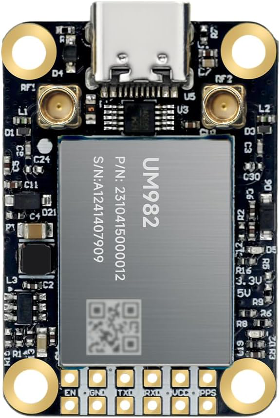
 Design with MJ UM982 RTK GPS in Cirkit Designer
Introduction
The MJ UM982 RTK GPS is a high-precision global positioning system module manufactured by Mengjie, with the part ID MJRTK-UM982. This module is designed for real-time kinematic (RTK) applications, offering centimeter-level positioning accuracy. It is ideal for use in applications such as surveying, precision agriculture, autonomous vehicles, and geospatial mapping. The MJ UM982 supports multiple satellite constellations, ensuring robust and reliable performance even in challenging environments.
Explore Projects Built with MJ UM982 RTK GPS
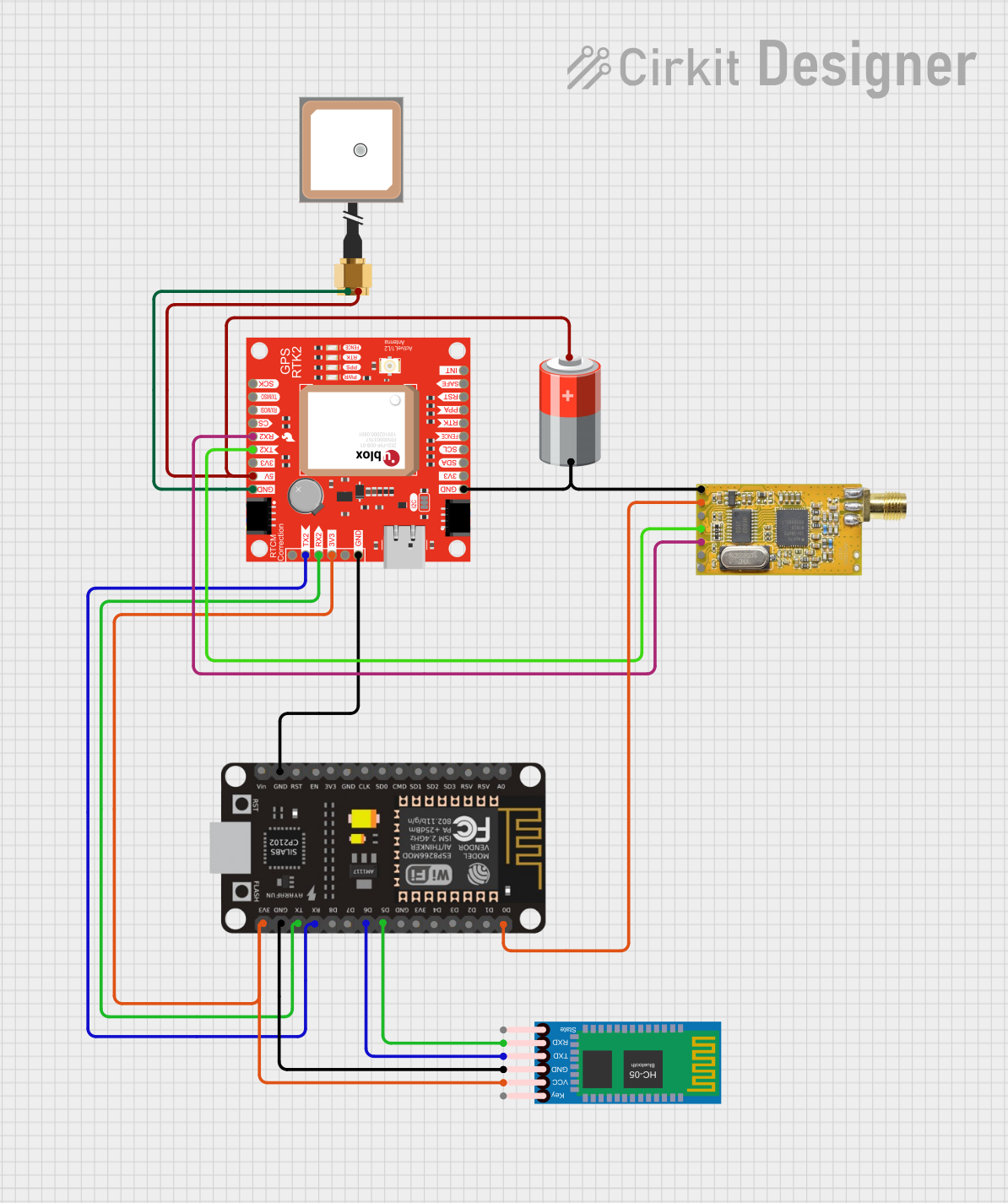 Open Project in Cirkit Designer
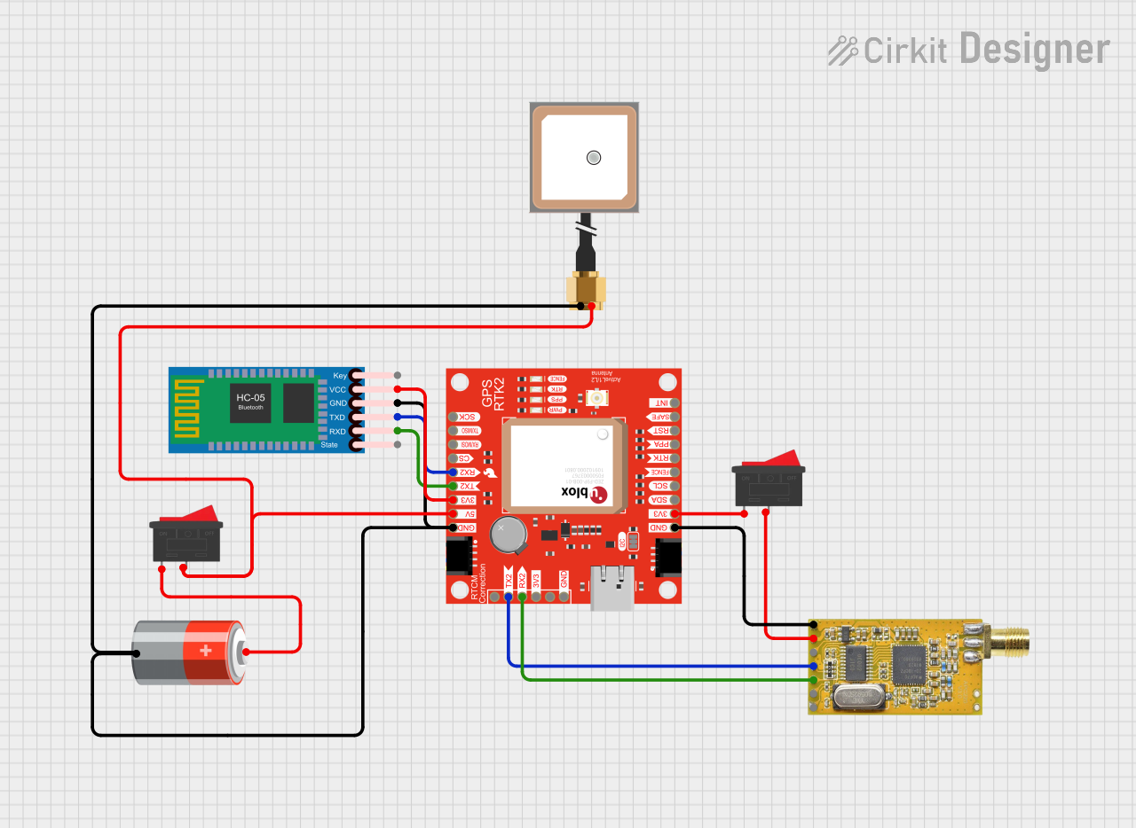 Open Project in Cirkit Designer
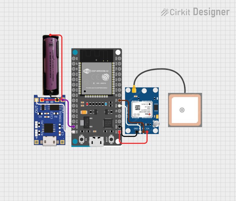 Open Project in Cirkit Designer
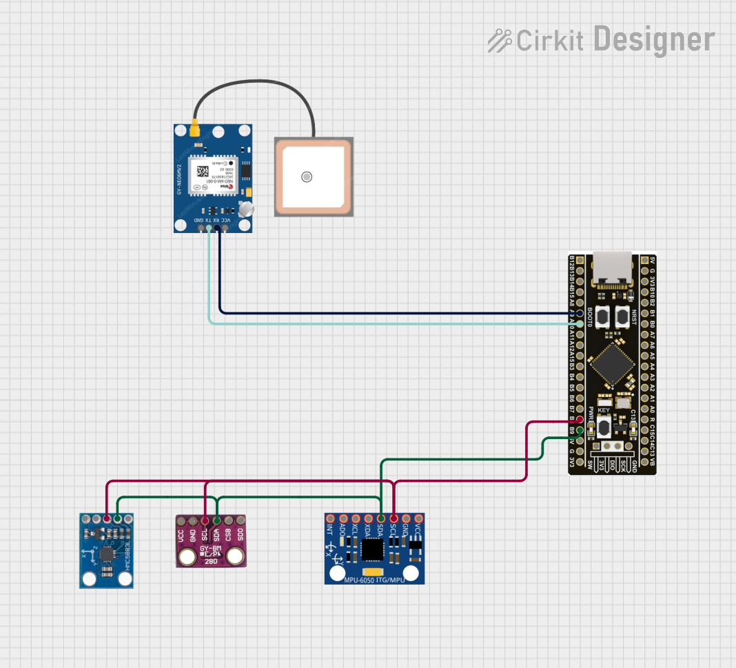 Open Project in Cirkit Designer
Explore Projects Built with MJ UM982 RTK GPS
Open Project in Cirkit DesignerOpen Project in Cirkit DesignerOpen Project in Cirkit DesignerOpen Project in Cirkit DesignerTechnical Specifications
Below are the key technical details of the MJ UM982 RTK GPS module:
General Specifications
| Parameter | Value |
|---|---|
| Manufacturer | Mengjie |
| Part ID | MJRTK-UM982 |
| Positioning Technology | RTK (Real-Time Kinematic) |
| Supported GNSS Systems | GPS, GLONASS, Galileo, BeiDou |
| Positioning Accuracy | RTK: ±1 cm + 1 ppm (horizontal) |
| Update Rate | Up to 10 Hz |
| Communication Interfaces | UART, I2C, SPI |
| Operating Voltage | 3.3V - 5.0V |
| Power Consumption | < 500 mW |
| Operating Temperature | -40°C to +85°C |
| Dimensions | 30 mm x 40 mm x 5 mm |
Pin Configuration and Descriptions
The MJ UM982 RTK GPS module has a 10-pin interface. The pin configuration is as follows:
| Pin Number | Pin Name | Description |
|---|---|---|
| 1 | VCC | Power supply input (3.3V - 5.0V) |
| 2 | GND | Ground |
| 3 | TX | UART Transmit (data output) |
| 4 | RX | UART Receive (data input) |
| 5 | SCL | I2C Clock |
| 6 | SDA | I2C Data |
| 7 | SPI_MISO | SPI Master-In-Slave-Out |
| 8 | SPI_MOSI | SPI Master-Out-Slave-In |
| 9 | SPI_CLK | SPI Clock |
| 10 | PPS | Pulse Per Second (timing synchronization) |
Usage Instructions
How to Use the MJ UM982 RTK GPS in a Circuit
- Power Supply: Connect the VCC pin to a regulated 3.3V or 5.0V power source and the GND pin to ground.
- Communication Interface: Choose a communication protocol (UART, I2C, or SPI) based on your application:
- For UART, connect the TX and RX pins to the corresponding UART pins on your microcontroller.
- For I2C, connect the SCL and SDA pins to the I2C bus.
- For SPI, connect the SPI_MISO, SPI_MOSI, and SPI_CLK pins to the SPI bus.
- Antenna Connection: Attach an external GNSS antenna to the module's antenna port for optimal signal reception.
- RTK Base Station: If using RTK mode, configure the module to receive correction data from an RTK base station via UART or another supported interface.
- Pulse Per Second (PPS): Use the PPS pin for precise timing synchronization if required.
Important Considerations and Best Practices
- Antenna Placement: Ensure the GNSS antenna has a clear view of the sky for optimal satellite reception.
- Power Supply: Use a stable and noise-free power source to avoid interference with the GPS signal.
- RTK Corrections: For RTK applications, ensure the module is configured to receive correction data from a compatible base station.
- Firmware Updates: Periodically check for firmware updates from Mengjie to ensure optimal performance and compatibility.
Example: Connecting to an Arduino UNO
Below is an example of how to connect the MJ UM982 RTK GPS module to an Arduino UNO using UART:
Wiring
| MJ UM982 Pin | Arduino UNO Pin |
|---|---|
| VCC | 5V |
| GND | GND |
| TX | RX (Pin 0) |
| RX | TX (Pin 1) |
Arduino Code
#include <SoftwareSerial.h>

// Define RX and TX pins for the GPS module
SoftwareSerial gpsSerial(10, 11); // RX = Pin 10, TX = Pin 11

void setup() {
  Serial.begin(9600); // Initialize Serial Monitor
  gpsSerial.begin(9600); // Initialize GPS module communication

  Serial.println("MJ UM982 RTK GPS Module Test");
}

void loop() {
  // Check if data is available from the GPS module
  while (gpsSerial.available()) {
    char gpsData = gpsSerial.read(); // Read one character from GPS module
    Serial.print(gpsData); // Print the character to the Serial Monitor
  }
}
Notes
- Replace
10and11in theSoftwareSerialdefinition with the desired pins if needed. - Ensure the Arduino UNO's hardware UART (pins 0 and 1) is free if using
Serialfor debugging.
Troubleshooting and FAQs
Common Issues and Solutions
No GPS Fix:
- Cause: Poor antenna placement or obstructed view of the sky.
- Solution: Place the antenna in an open area with a clear view of the sky.
No Data Output:
- Cause: Incorrect wiring or baud rate mismatch.
- Solution: Verify the connections and ensure the baud rate matches the module's default (9600 bps).
RTK Corrections Not Working:
- Cause: Incorrect configuration or missing correction data.
- Solution: Check the RTK base station settings and ensure the module is receiving correction data.
High Power Consumption:
- Cause: Module operating in high-performance mode.
- Solution: Use power-saving modes if supported by your application.
FAQs
Q: Can the MJ UM982 operate without an RTK base station?
A: Yes, the module can operate in standalone mode, but the positioning accuracy will be reduced to standard GNSS levels.Q: What is the maximum update rate of the module?
A: The MJ UM982 supports an update rate of up to 10 Hz.Q: Does the module support multiple GNSS constellations simultaneously?
A: Yes, the module can track GPS, GLONASS, Galileo, and BeiDou satellites concurrently.Q: How do I update the firmware?
A: Firmware updates can be performed via the UART interface using the manufacturer's update tool.
This concludes the documentation for the MJ UM982 RTK GPS module. For further assistance, refer to the manufacturer's datasheet or support resources.