How to Use TPS22908EVM: Examples, Pinouts, and Specs
Introduction
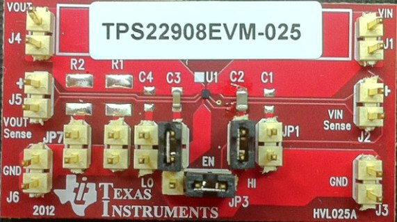
The TPS22908EVM is an evaluation module designed to demonstrate the performance and functionality of the TPS22908, a low RON load switch from Texas Instruments. This module is ideal for evaluating the TPS22908 in power management applications, particularly in portable and battery-powered devices. The TPS22908 features a small footprint, low quiescent current, and fast turn-on time, making it suitable for applications requiring efficient power delivery and minimal power loss.
Explore Projects Built with TPS22908EVM


Explore Projects Built with TPS22908EVM
Common Applications and Use Cases
- Smartphones and tablets
- Wearable devices
- Portable medical equipment
- Battery-powered IoT devices
- Power distribution in low-voltage systems
Technical Specifications
Key Technical Details
- Input Voltage Range: 0.8 V to 5.5 V
- Maximum Continuous Current: 2 A
- On-Resistance (RON): 44 mΩ at 1.8 V
- Quiescent Current: 29 µA (typical)
- Turn-On Time: 85 µs at 1.8 V
- Operating Temperature Range: -40°C to 85°C
- Package: 4-pin WCSP (0.8 mm x 0.8 mm)
Pin Configuration and Descriptions
The TPS22908EVM includes test points and connectors for easy evaluation of the TPS22908. Below is the pin configuration for the TPS22908 IC:
| Pin Name | Pin Number | Description |
|---|---|---|
| VIN | 1 | Input voltage to the load switch |
| VOUT | 2 | Output voltage from the load switch |
| GND | 3 | Ground connection |
| ON | 4 | Enable pin to turn the load switch on or off |
The evaluation module provides additional test points for monitoring input/output voltages and currents, as well as for controlling the ON pin.
Usage Instructions
How to Use the TPS22908EVM in a Circuit
Power Supply Connection:
- Connect the input voltage source to the VIN test point.
- Ensure the input voltage is within the range of 0.8 V to 5.5 V.
- Connect the ground of the power supply to the GND test point.
Load Connection:
- Connect the load to the VOUT test point.
- Ensure the load does not exceed the maximum continuous current of 2 A.
Enable the Load Switch:
- Use the ON test point to control the load switch.
- Apply a voltage of 1.0 V or higher to the ON pin to enable the switch.
- Pull the ON pin to ground to disable the switch.
Monitor Performance:
- Use the test points to measure input/output voltages and currents.
- Evaluate the switch's performance under different load conditions.
Important Considerations and Best Practices
- Ensure the input voltage does not exceed the maximum rating of 5.5 V to avoid damaging the device.
- Use low-resistance connections to minimize voltage drops and ensure accurate measurements.
- Avoid exceeding the maximum continuous current of 2 A to prevent overheating or damage.
- For fast switching applications, ensure the ON pin is driven with a clean and stable signal.
Example: Using TPS22908EVM with Arduino UNO
The TPS22908EVM can be controlled using an Arduino UNO to toggle the load switch. Below is an example code snippet:
// Define the ON pin connected to the Arduino
const int onPin = 7; // Connect Arduino pin 7 to the ON pin of TPS22908EVM

void setup() {
  pinMode(onPin, OUTPUT); // Set the ON pin as an output
}

void loop() {
  digitalWrite(onPin, HIGH); // Turn on the load switch
  delay(1000);               // Keep the switch on for 1 second
  digitalWrite(onPin, LOW);  // Turn off the load switch
  delay(1000);               // Keep the switch off for 1 second
}
Note: Ensure the Arduino's output voltage is compatible with the ON pin's logic level requirements (1.0 V or higher to enable the switch).
Troubleshooting and FAQs
Common Issues and Solutions
The load switch does not turn on:
- Verify that the ON pin is receiving a voltage of 1.0 V or higher.
- Check the input voltage at the VIN test point to ensure it is within the specified range.
- Ensure the ground connections are secure.
Output voltage is lower than expected:
- Check for excessive load current that may cause a voltage drop.
- Verify the input voltage and ensure it is stable.
- Inspect the connections for high resistance or loose contacts.
The device overheats:
- Ensure the load current does not exceed the maximum continuous current of 2 A.
- Verify that the input voltage is within the specified range.
- Check for short circuits at the output.
No output voltage when the switch is enabled:
- Confirm that the load is properly connected to the VOUT test point.
- Check the ON pin signal to ensure it is correctly toggled.
FAQs
Q1: Can the TPS22908EVM handle inrush current during startup?
A1: Yes, the TPS22908 is designed to handle inrush current during startup. However, ensure the load capacitance is within the recommended range to avoid excessive inrush current.
Q2: What is the maximum load capacitance supported by the TPS22908?
A2: The TPS22908 can support load capacitances up to 100 µF. For higher capacitances, additional precautions such as inrush current limiting may be required.
Q3: Can the TPS22908EVM be used with a 3.3 V logic system?
A3: Yes, the ON pin is compatible with 3.3 V logic levels, making it suitable for use with most microcontrollers and logic systems.
Q4: Is the TPS22908EVM suitable for high-frequency switching applications?
A4: The TPS22908 has a fast turn-on time of 85 µs, making it suitable for many low-frequency switching applications. For high-frequency switching, ensure the ON pin signal is stable and noise-free.
This concludes the documentation for the TPS22908EVM. For further details, refer to the official Texas Instruments datasheet and user guide.