Cirkit Designer Logo
Cirkit Designer
Your all-in-one circuit design IDE
Home / 
Component Documentation

How to Use esp32 UWB: Examples, Pinouts, and Specs

Image of esp32 UWB
Cirkit Designer LogoDesign with esp32 UWB in Cirkit Designer

Introduction

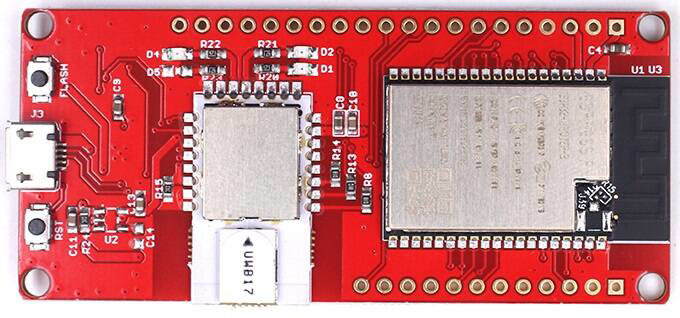
The ESP32 UWB (Ultra-Wideband) is a microcontroller developed by Demo, with the part ID Esp32 DW3000(UWB). This component integrates UWB technology, enabling precise location tracking and short-range communication. It also features Wi-Fi and Bluetooth capabilities, making it a versatile choice for IoT applications. The ESP32 UWB is particularly suited for scenarios requiring high positioning accuracy and low power consumption.

Explore Projects Built with esp32 UWB

Use Cirkit Designer to design, explore, and prototype these projects online. Some projects support real-time simulation. Click "Open Project" to start designing instantly!
ESP32-Based RF Communication System with 433 MHz Modules
Image of 433 mhz: A project utilizing esp32 UWB in a practical application
This circuit comprises an ESP32 microcontroller connected to a 433 MHz RF transmitter and receiver pair. The ESP32 is programmed to receive and decode RF signals through the receiver module, as well as send RF signals via the transmitter module. Additionally, the ESP32 can communicate with a Bluetooth device to exchange commands and data, and it uses an LED for status indication.
Cirkit Designer LogoOpen Project in Cirkit Designer
ESP32 and NRF24L01 Wireless Control Circuit
Image of master Node: A project utilizing esp32 UWB in a practical application
This circuit features an ESP32-WROOM-32UE microcontroller interfaced with an NRF24L01 wireless transceiver module, allowing for wireless communication capabilities. A pushbutton with a pull-down resistor is connected to the ESP32 for user input. Power regulation is managed by an AMS1117 3.3V regulator, which receives 5V from an AC-DC PSU board and is stabilized by an electrolytic capacitor, providing a stable 3.3V supply to the ESP32 and NRF24L01.
Cirkit Designer LogoOpen Project in Cirkit Designer
ESP32-Based Multi-Sensor Health Monitoring System with Bluetooth Connectivity
Image of circuit diagram: A project utilizing esp32 UWB in a practical application
This circuit features an ESP32-WROOM-32UE microcontroller as the central processing unit, interfacing with a variety of sensors and modules. It includes a MAX30100 pulse oximeter and heart-rate sensor, an MLX90614 infrared thermometer, an HC-05 Bluetooth module for wireless communication, and a Neo 6M GPS module for location tracking. All components are powered by a common voltage supply and are connected to specific GPIO pins on the ESP32 for data exchange, with the sensors using I2C communication and the modules using UART.
Cirkit Designer LogoOpen Project in Cirkit Designer
ESP32-Based Environmental Data Logger with GPS and RF Communication
Image of Sat: A project utilizing esp32 UWB in a practical application
This circuit features an ESP32-WROOM-32UE microcontroller as its central processing unit, interfaced with a variety of sensors including a BMP280 barometric pressure sensor, an Adafruit VEML6075 UV sensor, an ENS160+AHT21 air quality sensor, and a GPS NEO 6M module for location tracking. The ESP32 logs data from these sensors to an SD card using a SparkFun OpenLog and also communicates with an RFM95 LoRa transceiver for wireless data transmission. A step-up boost converter raises the voltage from a 3.7V battery to 5V to power the ESP32-CAM, and a buzzer is included for audio signaling, all controlled by the ESP32 which runs a sketch to read sensor data and log it periodically.
Cirkit Designer LogoOpen Project in Cirkit Designer

Explore Projects Built with esp32 UWB

Use Cirkit Designer to design, explore, and prototype these projects online. Some projects support real-time simulation. Click "Open Project" to start designing instantly!
Image of 433 mhz: A project utilizing esp32 UWB in a practical application
ESP32-Based RF Communication System with 433 MHz Modules
This circuit comprises an ESP32 microcontroller connected to a 433 MHz RF transmitter and receiver pair. The ESP32 is programmed to receive and decode RF signals through the receiver module, as well as send RF signals via the transmitter module. Additionally, the ESP32 can communicate with a Bluetooth device to exchange commands and data, and it uses an LED for status indication.
Cirkit Designer LogoOpen Project in Cirkit Designer
Image of master Node: A project utilizing esp32 UWB in a practical application
ESP32 and NRF24L01 Wireless Control Circuit
This circuit features an ESP32-WROOM-32UE microcontroller interfaced with an NRF24L01 wireless transceiver module, allowing for wireless communication capabilities. A pushbutton with a pull-down resistor is connected to the ESP32 for user input. Power regulation is managed by an AMS1117 3.3V regulator, which receives 5V from an AC-DC PSU board and is stabilized by an electrolytic capacitor, providing a stable 3.3V supply to the ESP32 and NRF24L01.
Cirkit Designer LogoOpen Project in Cirkit Designer
Image of circuit diagram: A project utilizing esp32 UWB in a practical application
ESP32-Based Multi-Sensor Health Monitoring System with Bluetooth Connectivity
This circuit features an ESP32-WROOM-32UE microcontroller as the central processing unit, interfacing with a variety of sensors and modules. It includes a MAX30100 pulse oximeter and heart-rate sensor, an MLX90614 infrared thermometer, an HC-05 Bluetooth module for wireless communication, and a Neo 6M GPS module for location tracking. All components are powered by a common voltage supply and are connected to specific GPIO pins on the ESP32 for data exchange, with the sensors using I2C communication and the modules using UART.
Cirkit Designer LogoOpen Project in Cirkit Designer
Image of Sat: A project utilizing esp32 UWB in a practical application
ESP32-Based Environmental Data Logger with GPS and RF Communication
This circuit features an ESP32-WROOM-32UE microcontroller as its central processing unit, interfaced with a variety of sensors including a BMP280 barometric pressure sensor, an Adafruit VEML6075 UV sensor, an ENS160+AHT21 air quality sensor, and a GPS NEO 6M module for location tracking. The ESP32 logs data from these sensors to an SD card using a SparkFun OpenLog and also communicates with an RFM95 LoRa transceiver for wireless data transmission. A step-up boost converter raises the voltage from a 3.7V battery to 5V to power the ESP32-CAM, and a buzzer is included for audio signaling, all controlled by the ESP32 which runs a sketch to read sensor data and log it periodically.
Cirkit Designer LogoOpen Project in Cirkit Designer

Common Applications and Use Cases

  • Indoor navigation and positioning systems
  • Asset tracking in warehouses and factories
  • Proximity-based access control
  • Smart home automation
  • Real-time location systems (RTLS)
  • IoT devices requiring precise spatial awareness

Technical Specifications

Key Technical Details

Parameter Value
Manufacturer Demo
Part ID Esp32 DW3000(UWB)
Microcontroller Core Dual-core Xtensa LX6
UWB Frequency Range 3.1 GHz to 10.6 GHz
UWB Data Rate Up to 6.8 Mbps
Wi-Fi Standard 802.11 b/g/n
Bluetooth Version Bluetooth 4.2 (BLE)
Operating Voltage 3.3V
Power Consumption Low power (varies by mode)
Positioning Accuracy ±10 cm
Operating Temperature -40°C to +85°C
Dimensions 18 mm x 25 mm

Pin Configuration and Descriptions

Pin Number Pin Name Description
1 VCC Power supply input (3.3V)
2 GND Ground
3 TXD UART Transmit Data
4 RXD UART Receive Data
5 GPIO0 General Purpose I/O Pin 0
6 GPIO1 General Purpose I/O Pin 1
7 SPI_MOSI SPI Master Out Slave In
8 SPI_MISO SPI Master In Slave Out
9 SPI_CLK SPI Clock
10 SPI_CS SPI Chip Select
11 UWB_TX UWB Transmit
12 UWB_RX UWB Receive
13 RESET Reset Pin
14 EN Enable Pin (used to wake the module)

Usage Instructions

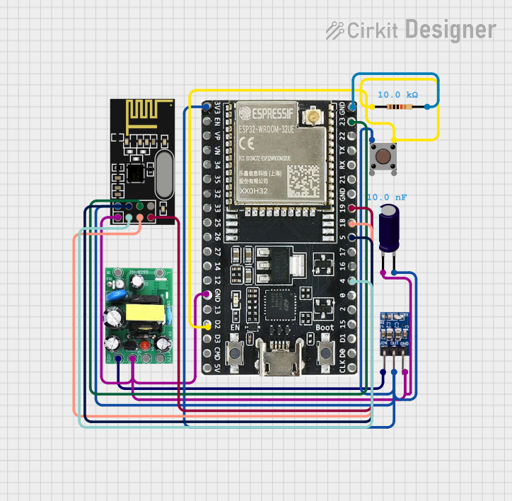
How to Use the ESP32 UWB in a Circuit

  1. Power Supply: Connect the VCC pin to a 3.3V power source and GND to ground.
  2. Communication Interface: Use UART or SPI for communication with a microcontroller or host device.
  3. UWB Antenna: Ensure the UWB antenna is properly connected and positioned for optimal signal transmission and reception.
  4. GPIO Pins: Configure GPIO pins as needed for additional functionality, such as controlling LEDs or reading sensors.
  5. Reset and Enable: Use the RESET pin to restart the module and the EN pin to wake it from sleep mode.

Important Considerations and Best Practices

  • Power Supply: Ensure a stable 3.3V power supply to avoid damage or erratic behavior.
  • Antenna Placement: Place the UWB antenna in an open area, away from metal objects, to minimize interference.
  • Heat Management: Operate the module within the specified temperature range (-40°C to +85°C) to prevent overheating.
  • Firmware Updates: Regularly update the firmware to ensure compatibility and access to the latest features.

Example: Connecting ESP32 UWB to Arduino UNO

Below is an example of how to connect and use the ESP32 UWB with an Arduino UNO for basic communication:

Wiring Diagram

ESP32 UWB Pin Arduino UNO Pin
VCC 3.3V
GND GND
TXD RX (Pin 0)
RXD TX (Pin 1)

Arduino Code Example

#include <SoftwareSerial.h>

// Define RX and TX pins for SoftwareSerial
SoftwareSerial UWBSerial(10, 11); // RX = Pin 10, TX = Pin 11

void setup() {
  // Initialize serial communication with the ESP32 UWB
  Serial.begin(9600); // Communication with PC
  UWBSerial.begin(115200); // Communication with ESP32 UWB

  Serial.println("ESP32 UWB Test Initialized");
}

void loop() {
  // Check if data is available from the ESP32 UWB
  if (UWBSerial.available()) {
    String data = UWBSerial.readString();
    Serial.print("Received from ESP32 UWB: ");
    Serial.println(data);
  }

  // Send data to the ESP32 UWB
  if (Serial.available()) {
    String command = Serial.readString();
    UWBSerial.println(command);
    Serial.print("Sent to ESP32 UWB: ");
    Serial.println(command);
  }
}

Troubleshooting and FAQs

Common Issues and Solutions

  1. No Communication with Host Device

    • Cause: Incorrect wiring or baud rate mismatch.
    • Solution: Double-check the wiring and ensure the baud rate in the code matches the ESP32 UWB's default baud rate.
  2. Inaccurate Positioning

    • Cause: Poor antenna placement or interference.
    • Solution: Reposition the antenna in an open area, away from metal objects or other sources of interference.
  3. Module Not Powering On

    • Cause: Insufficient or unstable power supply.
    • Solution: Verify the power source provides a stable 3.3V and sufficient current.
  4. Overheating

    • Cause: Operating outside the recommended temperature range.
    • Solution: Ensure the module is used within the specified temperature range (-40°C to +85°C).

FAQs

Q1: Can the ESP32 UWB be used outdoors?
A1: Yes, but ensure the module is protected from environmental factors like moisture and extreme temperatures.

Q2: What is the maximum range of the UWB communication?
A2: The maximum range is approximately 10-50 meters, depending on the environment and antenna configuration.

Q3: Can I use the ESP32 UWB with other microcontrollers?
A3: Yes, the module supports UART and SPI interfaces, making it compatible with most microcontrollers.

Q4: How do I update the firmware?
A4: Firmware updates can be performed via the UART interface using the manufacturer's update tool. Refer to the official documentation for detailed instructions.