Cirkit Designer Logo
Cirkit Designer
Your all-in-one circuit design IDE
Home / 
Component Documentation

How to Use VL53L0X: Examples, Pinouts, and Specs

Image of VL53L0X
Cirkit Designer LogoDesign with VL53L0X in Cirkit Designer

Introduction

The VL53L0X is a state-of-the-art Time-of-Flight (ToF) laser-ranging sensor that provides accurate distance measurements up to 2 meters. It operates by emitting a very short infrared laser pulse and then measuring the time it takes for the light to bounce back from a target. This technology allows for precise and reliable distance sensing, making it ideal for a wide range of applications such as obstacle detection in robotics, user detection for personal computers and IoT devices, and autofocus in digital cameras.

Explore Projects Built with VL53L0X

Use Cirkit Designer to design, explore, and prototype these projects online. Some projects support real-time simulation. Click "Open Project" to start designing instantly!
Arduino UNO with A9G GSM/GPRS and Dual VL53L1X Distance Sensors
Image of TED CIRCUIT : A project utilizing VL53L0X in a practical application
This circuit features an Arduino UNO microcontroller interfaced with an A9G GSM/GPRS+GPS/BDS module and two VL53L1X time-of-flight distance sensors. The A9G module is connected to the Arduino via serial communication for GPS and GSM functionalities, while both VL53L1X sensors are connected through I2C with shared SDA and SCL lines and individual SHUT pins for selective sensor activation. The Arduino is programmed to control these peripherals, although the specific functionality is not detailed in the provided code.
Cirkit Designer LogoOpen Project in Cirkit Designer
Arduino UNO R4 WiFi Laser Module with Distance Sensor
Image of KIT 1: SENSOR KIT: A project utilizing VL53L0X in a practical application
This circuit features an Arduino UNO R4 WiFi connected to a VL53L0X distance sensor via I2C for distance measurement. Additionally, a tube laser module is powered by a battery case and controlled through a rocker switch, with a terminal block connector completing the circuit.
Cirkit Designer LogoOpen Project in Cirkit Designer
ESP8266 NodeMCU-Based Smart Eye Pressure Monitor with OLED Display and Wi-Fi Connectivity
Image of Copy of test 2 (7): A project utilizing VL53L0X in a practical application
This circuit features an ESP8266 NodeMCU microcontroller interfaced with a VL53L0X time-of-flight distance sensor, a 0.96" OLED display, a piezo sensor, and a photodiode for light detection. The ESP8266 collects data from the sensors, displays readings on the OLED, and hosts a web server to present the information. It is likely designed for distance measurement, light intensity detection, and pressure sensing, with the capability to monitor and display these parameters in real-time over WiFi.
Cirkit Designer LogoOpen Project in Cirkit Designer
Arduino Mega 2560-Based Multi-Sensor System with Distance, Magnetometer, and Camera Integration
Image of Junior Design - Sensors: A project utilizing VL53L0X in a practical application
This circuit features an Arduino Mega 2560 microcontroller interfaced with multiple VL53L0X distance sensors, an OV7725 camera module, and an Adafruit LIS3MDL triple-axis magnetometer. The Arduino reads data from these sensors and the camera, likely for a robotics or environmental sensing application, and processes the data for further use or transmission.
Cirkit Designer LogoOpen Project in Cirkit Designer

Explore Projects Built with VL53L0X

Use Cirkit Designer to design, explore, and prototype these projects online. Some projects support real-time simulation. Click "Open Project" to start designing instantly!
Image of TED CIRCUIT : A project utilizing VL53L0X in a practical application
Arduino UNO with A9G GSM/GPRS and Dual VL53L1X Distance Sensors
This circuit features an Arduino UNO microcontroller interfaced with an A9G GSM/GPRS+GPS/BDS module and two VL53L1X time-of-flight distance sensors. The A9G module is connected to the Arduino via serial communication for GPS and GSM functionalities, while both VL53L1X sensors are connected through I2C with shared SDA and SCL lines and individual SHUT pins for selective sensor activation. The Arduino is programmed to control these peripherals, although the specific functionality is not detailed in the provided code.
Cirkit Designer LogoOpen Project in Cirkit Designer
Image of KIT 1: SENSOR KIT: A project utilizing VL53L0X in a practical application
Arduino UNO R4 WiFi Laser Module with Distance Sensor
This circuit features an Arduino UNO R4 WiFi connected to a VL53L0X distance sensor via I2C for distance measurement. Additionally, a tube laser module is powered by a battery case and controlled through a rocker switch, with a terminal block connector completing the circuit.
Cirkit Designer LogoOpen Project in Cirkit Designer
Image of Copy of test 2 (7): A project utilizing VL53L0X in a practical application
ESP8266 NodeMCU-Based Smart Eye Pressure Monitor with OLED Display and Wi-Fi Connectivity
This circuit features an ESP8266 NodeMCU microcontroller interfaced with a VL53L0X time-of-flight distance sensor, a 0.96" OLED display, a piezo sensor, and a photodiode for light detection. The ESP8266 collects data from the sensors, displays readings on the OLED, and hosts a web server to present the information. It is likely designed for distance measurement, light intensity detection, and pressure sensing, with the capability to monitor and display these parameters in real-time over WiFi.
Cirkit Designer LogoOpen Project in Cirkit Designer
Image of Junior Design - Sensors: A project utilizing VL53L0X in a practical application
Arduino Mega 2560-Based Multi-Sensor System with Distance, Magnetometer, and Camera Integration
This circuit features an Arduino Mega 2560 microcontroller interfaced with multiple VL53L0X distance sensors, an OV7725 camera module, and an Adafruit LIS3MDL triple-axis magnetometer. The Arduino reads data from these sensors and the camera, likely for a robotics or environmental sensing application, and processes the data for further use or transmission.
Cirkit Designer LogoOpen Project in Cirkit Designer

Technical Specifications

Key Technical Details

  • Operating Voltage: 2.6V to 3.5V
  • Average Current Consumption: 20 mA (typical)
  • Peak Current Consumption: 40 mA (during laser pulse)
  • Maximum Range: Up to 2 meters
  • Resolution: 1 mm
  • Laser Wavelength: 940 nm (Invisible to the human eye)
  • Field of View: 25°
  • Interface: I2C
  • I2C Address: 0x29 (7-bit)

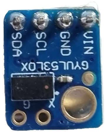
Pin Configuration and Descriptions

Pin Name Description
VIN Power supply (2.6V to 3.5V)
GND Ground
SCL I2C clock line
SDA I2C data line
GPIO1 Interrupt output (active low)
XSHUT Shutdown pin (active low)

Usage Instructions

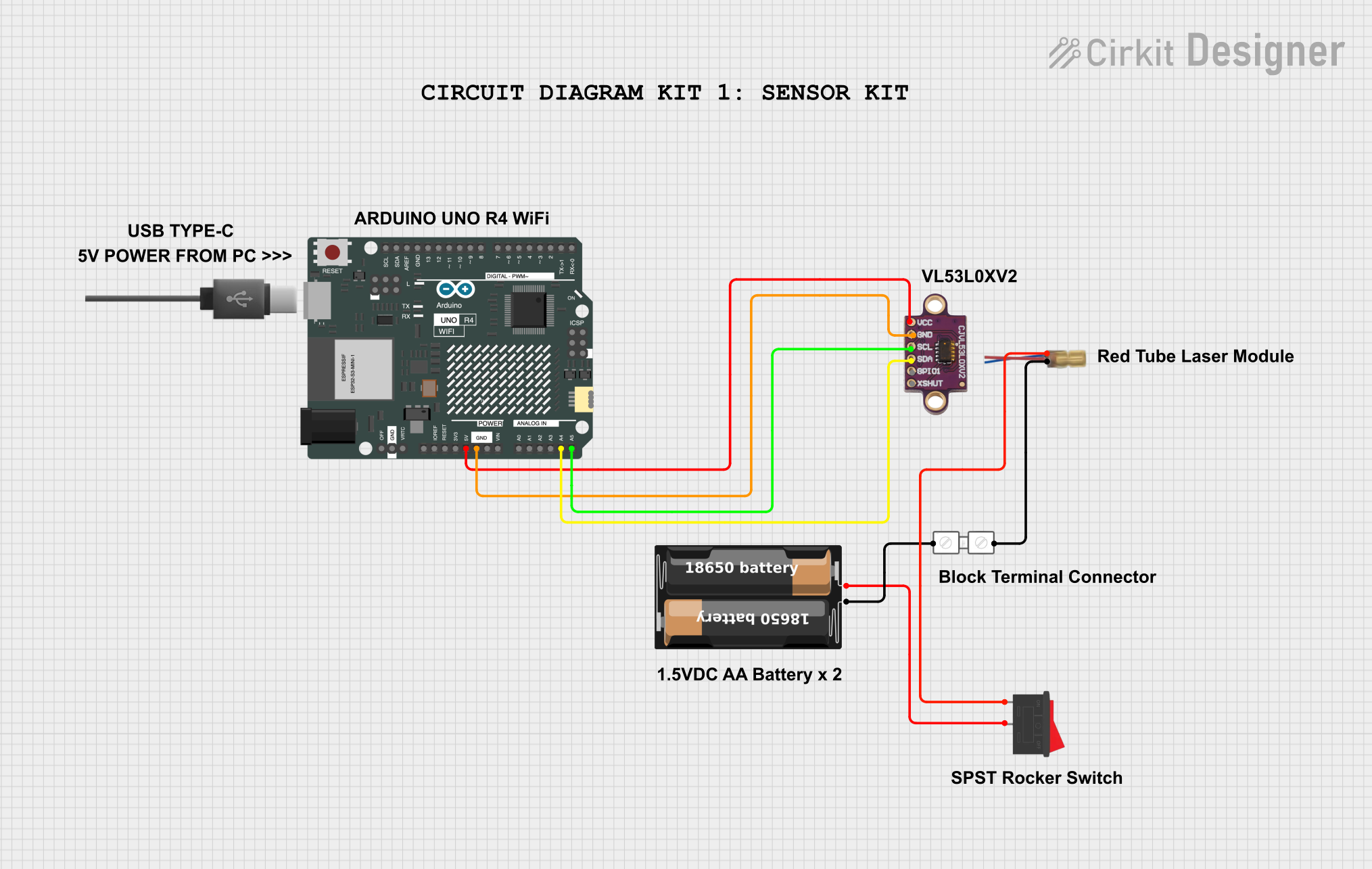
Integration into a Circuit

To use the VL53L0X in a circuit:

  1. Connect the VIN pin to a 2.6V to 3.5V power supply.
  2. Connect the GND pin to the ground of the power supply.
  3. Connect the SCL and SDA pins to the I2C clock and data lines, respectively.
  4. The GPIO1 pin can be used to receive hardware interrupts.
  5. The XSHUT pin can be used to power down the sensor for low-power consumption.

Best Practices

  • Ensure that the power supply is stable and within the specified voltage range.
  • Use pull-up resistors on the I2C lines if they are not already present on the microcontroller board.
  • Avoid exposing the sensor to direct sunlight or strong infrared sources to prevent measurement errors.
  • Keep the sensor lens clean and unobstructed.

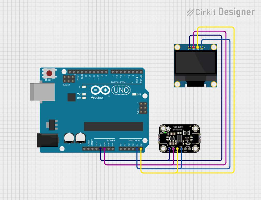
Example Code for Arduino UNO

#include <Wire.h>
#include <VL53L0X.h>

VL53L0X sensor;

void setup() {
  Serial.begin(9600);
  Wire.begin();

  sensor.init();
  sensor.setTimeout(500);
  sensor.startContinuous();
}

void loop() {
  Serial.print("Distance: ");
  Serial.print(sensor.readRangeContinuousMillimeters());
  if (sensor.timeoutOccurred()) { Serial.print(" TIMEOUT"); }
  Serial.println();
}

This example initializes the sensor and starts continuous distance measurements. The measured distance is printed to the serial monitor. If a timeout occurs (no response from the sensor), it prints "TIMEOUT".

Troubleshooting and FAQs

Common Issues

  • No Data: Ensure that the I2C connections are correct and that the sensor is powered.
  • Inaccurate Readings: Check for obstructions in front of the sensor and clean the lens.
  • Intermittent Operation: Verify that the power supply is stable and within the required voltage range.

FAQs

Q: Can the VL53L0X be used outdoors? A: The VL53L0X can be used outdoors but may be less accurate in direct sunlight.

Q: What is the maximum I2C speed the VL53L0X supports? A: The VL53L0X supports I2C speeds up to 400 kHz (Fast Mode).

Q: How can I change the I2C address of the sensor? A: The I2C address can be changed by writing to the I2C_SLAVE_DEVICE_ADDRESS register.

Q: Can the VL53L0X measure distances beyond 2 meters? A: The VL53L0X is optimized for distances up to 2 meters. Measurements beyond this range may be less accurate or unreliable.

For further assistance, consult the manufacturer's datasheet and application notes, which provide in-depth information on the VL53L0X's operation and advanced features.