How to Use Load Cell: Examples, Pinouts, and Specs
Introduction
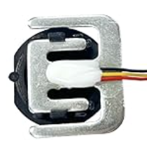
A load cell is a transducer that converts a force or weight into an electrical signal. It is widely used in applications requiring precise weight or force measurements, such as digital weighing scales, industrial automation systems, and material testing machines. Load cells are essential in industries like manufacturing, logistics, and healthcare, where accurate weight measurement is critical.
Common applications include:
- Digital weighing scales
- Industrial force measurement systems
- Robotics and automation
- Material testing equipment
- Tank and hopper weighing systems
Explore Projects Built with Load Cell

Explore Projects Built with Load Cell
Technical Specifications
Below are the general technical specifications for a typical load cell. Note that specific values may vary depending on the model and manufacturer.
Key Specifications
- Type: Strain gauge-based load cell
- Rated Load Capacity: 1 kg to 50 tons (varies by model)
- Output Signal: Millivolt per volt (mV/V), typically 1-3 mV/V
- Excitation Voltage: 5V to 15V DC (recommended 10V DC)
- Accuracy: ±0.02% to ±0.1% of full scale
- Non-linearity: ±0.03% of full scale
- Operating Temperature: -10°C to 50°C (typical)
- Material: Aluminum or stainless steel (depending on the model)
- Connector Type: 4-wire or 6-wire configuration
Pin Configuration
The pin configuration for a standard 4-wire load cell is as follows:
| Pin Name | Wire Color (Typical) | Description |
|---|---|---|
| E+ | Red | Positive excitation (V+) |
| E- | Black | Negative excitation (V-) |
| S+ | Green | Positive signal (output +) |
| S- | White | Negative signal (output -) |
For a 6-wire load cell, two additional wires are used for sense connections to compensate for voltage drops in long cables.
| Pin Name | Wire Color (Typical) | Description |
|---|---|---|
| E+ | Red | Positive excitation (V+) |
| E- | Black | Negative excitation (V-) |
| S+ | Green | Positive signal (output +) |
| S- | White | Negative signal (output -) |
| Sense+ | Blue | Positive sense |
| Sense- | Yellow | Negative sense |
Usage Instructions
How to Use a Load Cell in a Circuit
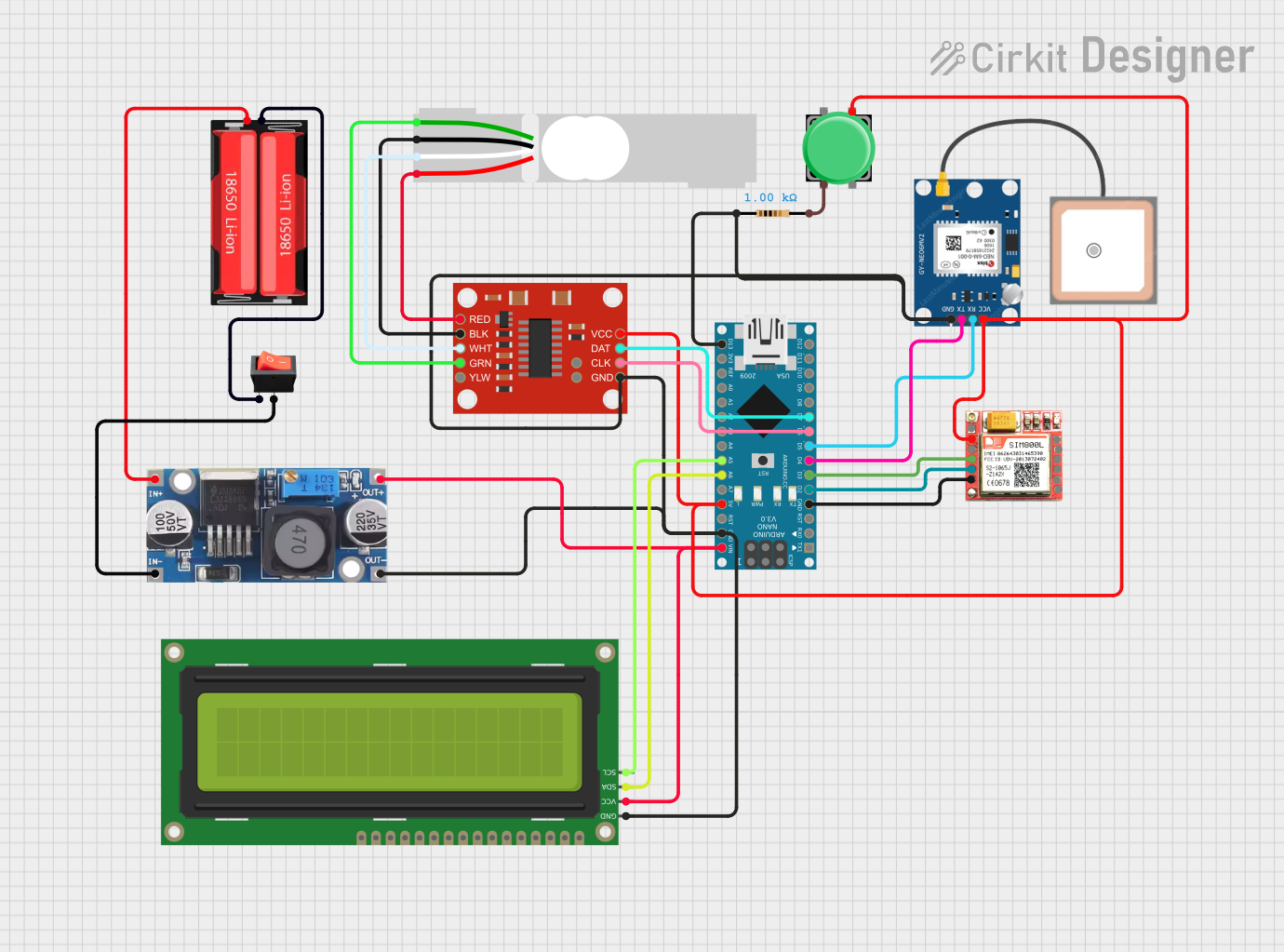
Connect the Load Cell to an Amplifier:
- Load cells produce very small signals (in mV). Use a signal amplifier, such as the HX711, to amplify the signal for further processing.
Wire the Load Cell:
- Connect the load cell wires to the amplifier module as per the pin configuration.
- For example, with the HX711 module:
- E+ (Red) → E+ on HX711
- E- (Black) → E- on HX711
- S+ (Green) → A+ on HX711
- S- (White) → A- on HX711
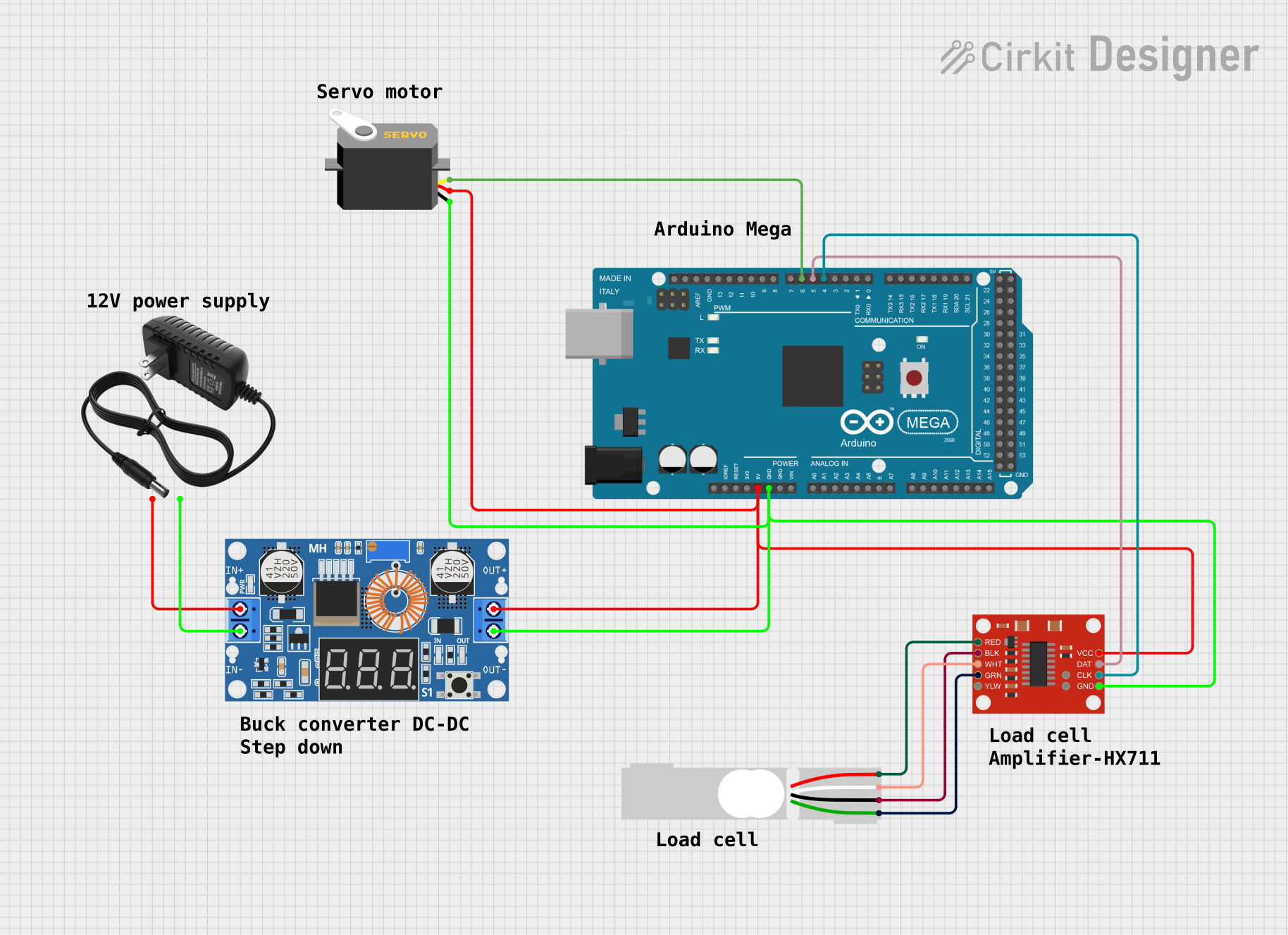
Connect the Amplifier to a Microcontroller:
- Connect the amplifier's data (DT) and clock (SCK) pins to the microcontroller's digital pins.
- Provide power to the amplifier module (e.g., 5V and GND).
Calibrate the Load Cell:
- Use a known weight to calibrate the load cell and determine the scale factor for accurate measurements.
Read Data:
- Use a microcontroller (e.g., Arduino UNO) to read the amplified signal and convert it into weight or force.
Important Considerations and Best Practices
- Calibration: Always calibrate the load cell before use to ensure accurate measurements.
- Mounting: Securely mount the load cell to avoid mechanical stress or misalignment, which can affect accuracy.
- Temperature Effects: Be aware of temperature variations, as they can influence the load cell's output.
- Overloading: Avoid exceeding the rated load capacity to prevent damage to the load cell.
- Shielding: Use shielded cables to minimize electrical noise interference.
Example Code for Arduino UNO
Below is an example of how to interface a load cell with an HX711 amplifier and an Arduino UNO:
#include "HX711.h"

// Define HX711 pins
#define DT_PIN 3  // Data pin connected to digital pin 3
#define SCK_PIN 2 // Clock pin connected to digital pin 2

HX711 scale;

void setup() {
  Serial.begin(9600); // Initialize serial communication
  scale.begin(DT_PIN, SCK_PIN); // Initialize HX711 with defined pins

  Serial.println("Calibrating... Place a known weight on the load cell.");
  delay(5000); // Wait for user to place a weight

  // Set the calibration factor (adjust based on your load cell and amplifier)
  scale.set_scale(2280.f); // Example calibration factor
  scale.tare(); // Reset the scale to 0

  Serial.println("Calibration complete. Ready to measure.");
}

void loop() {
  // Read weight from the load cell
  float weight = scale.get_units(10); // Average of 10 readings
  Serial.print("Weight: ");
  Serial.print(weight);
  Serial.println(" kg");

  delay(500); // Delay for stability
}
Note: Replace the calibration factor (2280.f) with the value determined during calibration for your specific setup.
Troubleshooting and FAQs
Common Issues and Solutions
No Output Signal:
- Check all connections, especially the wiring between the load cell and the amplifier.
- Ensure the amplifier is powered correctly.
Inaccurate Measurements:
- Recalibrate the load cell using a known weight.
- Verify that the load cell is not overloaded or misaligned.
Fluctuating Readings:
- Use shielded cables to reduce electrical noise.
- Ensure the load cell is mounted securely and not subject to vibrations.
No Response from HX711:
- Verify the data (DT) and clock (SCK) pin connections to the microcontroller.
- Ensure the HX711 library is correctly installed in your Arduino IDE.
FAQs
Q: Can I use a load cell without an amplifier?
A: No, the output signal of a load cell is too small to be read directly by a microcontroller. An amplifier like the HX711 is required.
Q: How do I determine the calibration factor?
A: Place a known weight on the load cell, read the raw value, and calculate the calibration factor by dividing the raw value by the known weight.
Q: Can I use multiple load cells in one system?
A: Yes, you can connect multiple load cells in a parallel configuration (e.g., in a Wheatstone bridge) or use multiple amplifiers for individual load cells.
Q: What happens if I overload the load cell?
A: Overloading can permanently damage the load cell, leading to inaccurate readings or complete failure. Always stay within the rated load capacity.