Cirkit Designer Logo
Cirkit Designer
Your all-in-one circuit design IDE
Home / 
Component Documentation

How to Use Adafruit Metro M0 Express: Examples, Pinouts, and Specs

Image of Adafruit Metro M0 Express
Cirkit Designer LogoDesign with Adafruit Metro M0 Express in Cirkit Designer

Introduction

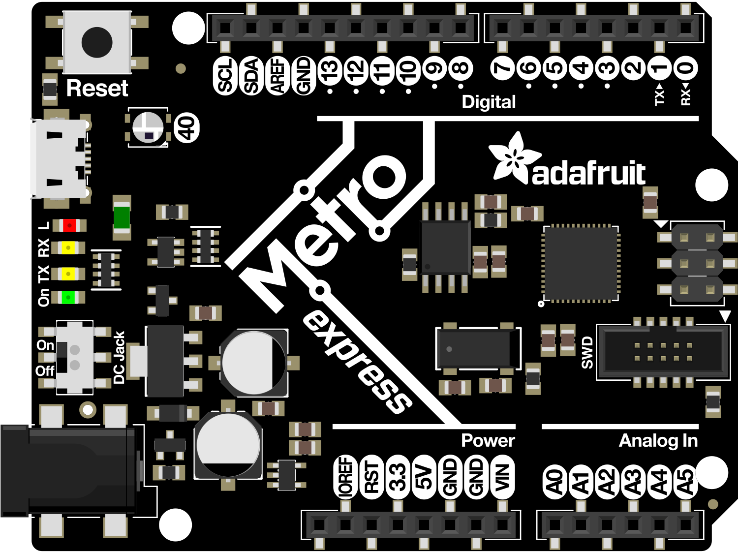
The Adafruit Metro M0 Express is a versatile and user-friendly development board designed for electronics enthusiasts and professionals alike. Based on the ATSAMD21G18 ARM Cortex M0+ microcontroller, this board is a powerhouse for prototyping and creating a wide array of electronics projects. With its extensive I/O capabilities, built-in USB connectivity, and compatibility with the Arduino Integrated Development Environment (IDE), the Metro M0 Express is an ideal platform for developing interactive objects, wearable technology, and IoT devices.

Explore Projects Built with Adafruit Metro M0 Express

Use Cirkit Designer to design, explore, and prototype these projects online. Some projects support real-time simulation. Click "Open Project" to start designing instantly!
Solar-Powered Environmental Data Logger with Adafruit Feather M0 Express
Image of Lake Thoreau Monitoring Station: A project utilizing Adafruit Metro M0 Express in a practical application
This circuit is designed for environmental data collection and logging, utilizing an Adafruit Feather M0 Express microcontroller as the central processing unit. It interfaces with a BME280 sensor for atmospheric temperature, humidity, and pressure measurements, an SGP30 sensor for monitoring air quality (eCO2 and TVOC), and a STEMMA soil sensor for detecting soil moisture and temperature. The system is powered by a solar panel and a 3.7v LiPo battery, managed by an Adafruit BQ24074 Solar-DC-USB Lipo Charger, and provides easy access to the microcontroller's connections through an Adafruit Terminal Breakout FeatherWing.
Cirkit Designer LogoOpen Project in Cirkit Designer
Multi-Sensor Health Monitoring System with Adafruit Feather M0 Adalogger
Image of health tracker: A project utilizing Adafruit Metro M0 Express in a practical application
This circuit is designed to interface multiple sensors with an Adafruit Feather M0 Adalogger microcontroller for data logging purposes. The sensors include a MAX30205 temperature sensor, a body dehydration sensor, a MAX30102 pulse oximeter, an Adafruit LSM6DSOX 6-axis accelerometer and gyroscope, and an Adafruit BME680 environmental sensor. All sensors are connected to the microcontroller via an I2C bus, sharing the SDA and SCL lines for communication.
Cirkit Designer LogoOpen Project in Cirkit Designer
I2C-Controlled OLED Display with External EEPROM and Interactive Pushbuttons
Image of godmode: A project utilizing Adafruit Metro M0 Express in a practical application
This is a microcontroller-based interactive device featuring a Wemos D1 Mini, an OLED display, external EEPROM, and an I/O expander. It includes user input buttons and status LEDs, with potential MIDI interface capabilities.
Cirkit Designer LogoOpen Project in Cirkit Designer
Battery-Powered Sensor Hub with Adafruit QT Py RP2040 and OLED Display
Image of 512: A project utilizing Adafruit Metro M0 Express in a practical application
This circuit features an Adafruit QT Py RP2040 microcontroller interfacing with an MPU-6050 accelerometer, an Adafruit APDS-9960 sensor, and a 0.96" OLED display via I2C communication. It is powered by a 3.7V LiPo battery and includes a green LED with a current-limiting resistor connected to an analog pin of the microcontroller.
Cirkit Designer LogoOpen Project in Cirkit Designer

Explore Projects Built with Adafruit Metro M0 Express

Use Cirkit Designer to design, explore, and prototype these projects online. Some projects support real-time simulation. Click "Open Project" to start designing instantly!
Image of Lake Thoreau Monitoring Station: A project utilizing Adafruit Metro M0 Express in a practical application
Solar-Powered Environmental Data Logger with Adafruit Feather M0 Express
This circuit is designed for environmental data collection and logging, utilizing an Adafruit Feather M0 Express microcontroller as the central processing unit. It interfaces with a BME280 sensor for atmospheric temperature, humidity, and pressure measurements, an SGP30 sensor for monitoring air quality (eCO2 and TVOC), and a STEMMA soil sensor for detecting soil moisture and temperature. The system is powered by a solar panel and a 3.7v LiPo battery, managed by an Adafruit BQ24074 Solar-DC-USB Lipo Charger, and provides easy access to the microcontroller's connections through an Adafruit Terminal Breakout FeatherWing.
Cirkit Designer LogoOpen Project in Cirkit Designer
Image of health tracker: A project utilizing Adafruit Metro M0 Express in a practical application
Multi-Sensor Health Monitoring System with Adafruit Feather M0 Adalogger
This circuit is designed to interface multiple sensors with an Adafruit Feather M0 Adalogger microcontroller for data logging purposes. The sensors include a MAX30205 temperature sensor, a body dehydration sensor, a MAX30102 pulse oximeter, an Adafruit LSM6DSOX 6-axis accelerometer and gyroscope, and an Adafruit BME680 environmental sensor. All sensors are connected to the microcontroller via an I2C bus, sharing the SDA and SCL lines for communication.
Cirkit Designer LogoOpen Project in Cirkit Designer
Image of godmode: A project utilizing Adafruit Metro M0 Express in a practical application
I2C-Controlled OLED Display with External EEPROM and Interactive Pushbuttons
This is a microcontroller-based interactive device featuring a Wemos D1 Mini, an OLED display, external EEPROM, and an I/O expander. It includes user input buttons and status LEDs, with potential MIDI interface capabilities.
Cirkit Designer LogoOpen Project in Cirkit Designer
Image of 512: A project utilizing Adafruit Metro M0 Express in a practical application
Battery-Powered Sensor Hub with Adafruit QT Py RP2040 and OLED Display
This circuit features an Adafruit QT Py RP2040 microcontroller interfacing with an MPU-6050 accelerometer, an Adafruit APDS-9960 sensor, and a 0.96" OLED display via I2C communication. It is powered by a 3.7V LiPo battery and includes a green LED with a current-limiting resistor connected to an analog pin of the microcontroller.
Cirkit Designer LogoOpen Project in Cirkit Designer

Common Applications and Use Cases

  • Educational projects and learning platforms
  • DIY electronics and hobbyist projects
  • Prototyping for product development
  • Interactive art installations
  • Wearable technology
  • Internet of Things (IoT) devices

Technical Specifications

Key Technical Details

  • Microcontroller: ATSAMD21G18 ARM Cortex M0+
  • Operating Voltage: 3.3V
  • Input Voltage: 6-16V
  • Digital I/O Pins: 25, with 12 PWM
  • Analog Input Pins: 6, 12-bit ADC channels
  • Analog Output Pins: 1, 10-bit DAC
  • Flash Memory: 256KB
  • SRAM: 32KB
  • Clock Speed: 48 MHz
  • USB: Micro-USB connector for programming and power
  • Dimensions: 72mm x 53mm x 19mm

Pin Configuration and Descriptions

Pin Number Function Description
1 Digital I/O General-purpose digital input/output pin
2-13 Digital I/O General-purpose digital input/output pins
14 Analog In Analog input pin (A0)
15-19 Analog In Analog input pins (A1-A5)
20 Analog Out Analog output pin (DAC)
21-25 Digital I/O Additional digital input/output pins
GND Ground Common ground for circuit
VIN Voltage Input Input voltage for the board (6-16V)
5V 5V Output Regulated 5V output pin
3V3 3.3V Output Regulated 3.3V output pin
RST Reset Resets the microcontroller

Usage Instructions

How to Use the Component in a Circuit

  1. Powering the Board: Connect a power source to the VIN pin for an external power supply, or use the USB connection for power and programming.
  2. Connecting I/O: Utilize the digital and analog pins to connect sensors, actuators, and other components. Ensure that the connected devices are compatible with the board's operating voltage.
  3. Programming: Use the Arduino IDE to write and upload sketches to the Metro M0 Express. Select "Adafruit Metro M0 Express" from the board manager.

Important Considerations and Best Practices

  • Always verify the power requirements of external components to prevent damage to the board.
  • When using PWM pins, ensure that the frequency and duty cycle are appropriate for the connected devices.
  • Utilize the onboard LED as a simple debugging tool to indicate the status of your program.
  • Take advantage of the board's built-in USB connectivity for easy programming and serial communication.

Troubleshooting and FAQs

Common Issues Users Might Face

  • Board Not Recognized: Ensure that the correct drivers are installed and that the USB cable is functioning properly.
  • Sketch Not Uploading: Check the board and port selections in the Arduino IDE. Press the reset button on the board if necessary.
  • Inconsistent Behavior: Verify that the power supply is stable and within the specified range.

Solutions and Tips for Troubleshooting

  • If the board is not recognized, try using a different USB port or cable.
  • For upload issues, double-check the connections and ensure that no other program is using the selected port.
  • Use a multimeter to check the power supply voltage and ensure it is within the acceptable range.

FAQs

Q: Can I use the Metro M0 Express with Arduino shields? A: Yes, the Metro M0 Express is compatible with many Arduino shields. However, verify the shield's voltage and pin compatibility.

Q: What programming languages can I use with the Metro M0 Express? A: The board is commonly programmed using C/C++ in the Arduino IDE, but it can also be used with other languages that support the ATSAMD21G18 microcontroller.

Q: How do I reset the board to factory settings? A: To reset the board, you can use the Arduino IDE to upload a blank sketch or press the reset button on the board twice quickly to enter bootloader mode.

Example Code for Arduino UNO

// Blink an LED connected to pin 13
void setup() {
  pinMode(13, OUTPUT); // Set pin 13 as an output
}

void loop() {
  digitalWrite(13, HIGH); // Turn the LED on
  delay(1000);           // Wait for a second
  digitalWrite(13, LOW);  // Turn the LED off
  delay(1000);           // Wait for a second
}

Note: The above code is a simple example to demonstrate the usage of the Metro M0 Express with the Arduino IDE. The onboard LED on the Metro M0 Express is also connected to pin 13, so this code will blink the onboard LED as well.