
How to Use ANKLE MPU6050 - GAIT: Examples, Pinouts, and Specs
 Design with ANKLE MPU6050 - GAIT in Cirkit Designer
Introduction
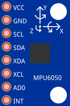
The ANKLE MPU6050 - GAIT is a 6-axis motion tracking device manufactured by InvenSense (Part ID: MPU-6050). It integrates a 3-axis gyroscope and a 3-axis accelerometer into a single chip, making it ideal for applications requiring precise motion and orientation tracking. This component is widely used in gait analysis to monitor ankle movement, providing critical data for rehabilitation, sports performance optimization, and biomechanical research.
Explore Projects Built with ANKLE MPU6050 - GAIT
 Open Project in Cirkit Designer
 Open Project in Cirkit Designer
 Open Project in Cirkit Designer
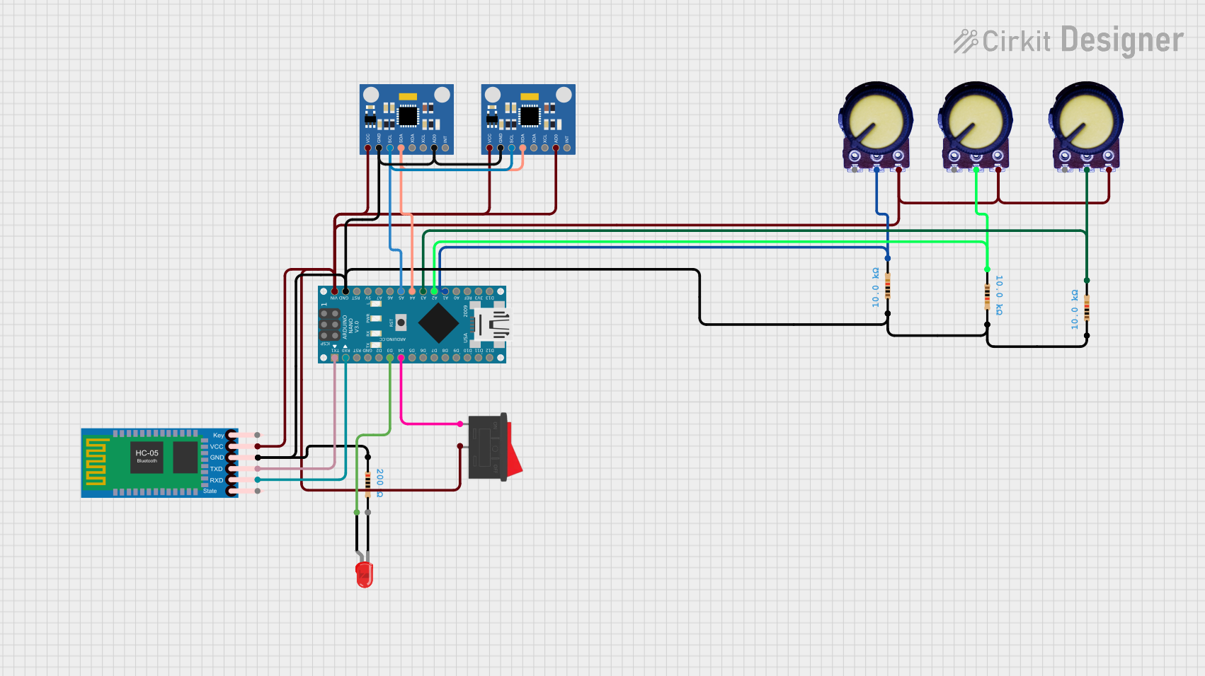 Open Project in Cirkit Designer
Explore Projects Built with ANKLE MPU6050 - GAIT
Open Project in Cirkit DesignerOpen Project in Cirkit DesignerOpen Project in Cirkit DesignerOpen Project in Cirkit DesignerCommon Applications
- Gait analysis for rehabilitation and physical therapy
- Sports performance monitoring and optimization
- Robotics and motion control systems
- Wearable devices for motion tracking
- Research in biomechanics and human movement
Technical Specifications
The following table outlines the key technical specifications of the MPU6050:
| Parameter | Value |
|---|---|
| Supply Voltage | 2.375V to 3.46V |
| Operating Current | 3.9 mA (typical) |
| Gyroscope Range | ±250, ±500, ±1000, ±2000 °/s |
| Accelerometer Range | ±2g, ±4g, ±8g, ±16g |
| Communication Interface | I2C (up to 400 kHz) |
| Operating Temperature | -40°C to +85°C |
| Dimensions | 4x4x0.9 mm (QFN package) |
Pin Configuration and Descriptions
The MPU6050 has 8 pins, as described in the table below:
| Pin | Name | Description |
|---|---|---|
| 1 | VDD | Power supply input (2.375V to 3.46V). |
| 2 | VLOGIC | Logic voltage reference for I/O pins (1.8V to VDD). |
| 3 | GND | Ground connection. |
| 4 | SCL | I2C clock input. |
| 5 | SDA | I2C data input/output. |
| 6 | AD0 | I2C address select (connect to GND for 0x68 or VDD for 0x69). |
| 7 | INT | Interrupt output (active high). |
| 8 | FSYNC | Frame synchronization input (optional, typically connected to GND). |
Usage Instructions
How to Use the MPU6050 in a Circuit
- Power Supply: Connect the VDD pin to a 3.3V power source and the GND pin to ground. If your microcontroller operates at 5V logic, use a level shifter for the I2C lines.
- I2C Communication: Connect the SCL and SDA pins to the corresponding I2C pins on your microcontroller. Use pull-up resistors (typically 4.7kΩ) on both lines.
- Address Selection: Set the I2C address by connecting the AD0 pin to either GND (address 0x68) or VDD (address 0x69).
- Interrupts (Optional): If needed, connect the INT pin to a GPIO pin on your microcontroller to handle interrupts.
- FSYNC (Optional): Leave the FSYNC pin unconnected or connect it to GND if not used.
Important Considerations
- Ensure the MPU6050 is mounted securely to minimize vibrations and noise in the measurements.
- Use decoupling capacitors (e.g., 0.1 µF) near the VDD pin to stabilize the power supply.
- Calibrate the gyroscope and accelerometer before use to improve accuracy.
- Avoid exposing the device to extreme temperatures or mechanical shocks.
Example Code for Arduino UNO
Below is an example of how to interface the MPU6050 with an Arduino UNO for gait analysis:
#include <Wire.h>
#include <MPU6050.h>

// Create an MPU6050 object
MPU6050 mpu;

// Variables to store sensor data
int16_t ax, ay, az; // Accelerometer data
int16_t gx, gy, gz; // Gyroscope data

void setup() {
  Serial.begin(9600); // Initialize serial communication
  Wire.begin();       // Initialize I2C communication

  // Initialize the MPU6050
  if (!mpu.begin(MPU6050_SCALE_2000DPS, MPU6050_RANGE_2G)) {
    Serial.println("Could not find a valid MPU6050 sensor, check connections!");
    while (1);
  }

  Serial.println("MPU6050 initialized successfully!");
}

void loop() {
  // Read accelerometer and gyroscope data
  mpu.getMotion6(&ax, &ay, &az, &gx, &gy, &gz);

  // Print the data to the Serial Monitor
  Serial.print("Accel: ");
  Serial.print("X="); Serial.print(ax);
  Serial.print(" Y="); Serial.print(ay);
  Serial.print(" Z="); Serial.print(az);
  Serial.print(" | Gyro: ");
  Serial.print("X="); Serial.print(gx);
  Serial.print(" Y="); Serial.print(gy);
  Serial.print(" Z="); Serial.println(gz);

  delay(100); // Delay for readability
}
Troubleshooting and FAQs
Common Issues
No Response from the MPU6050:
- Cause: Incorrect I2C address or wiring.
- Solution: Verify the AD0 pin connection and ensure the correct I2C address is used in the code.
Inaccurate Readings:
- Cause: Lack of calibration or excessive vibrations.
- Solution: Perform sensor calibration and ensure the device is securely mounted.
Device Overheating:
- Cause: Excessive current draw or improper power supply.
- Solution: Check the power supply voltage and current ratings.
I2C Communication Errors:
- Cause: Missing pull-up resistors or incorrect clock speed.
- Solution: Add 4.7kΩ pull-up resistors to the SDA and SCL lines and ensure the I2C clock speed is within the supported range.
FAQs
Q1: Can the MPU6050 be used with a 5V microcontroller?
A1: Yes, but you must use a logic level shifter for the I2C lines to prevent damage to the MPU6050.
Q2: How do I calibrate the MPU6050?
A2: Calibration involves collecting raw data while the device is stationary and calculating offsets for the gyroscope and accelerometer. Many libraries, such as the MPU6050 library for Arduino, include built-in calibration functions.
Q3: What is the maximum sampling rate of the MPU6050?
A3: The MPU6050 supports a maximum sampling rate of 1 kHz.
Q4: Can I use the MPU6050 for real-time gait analysis?
A4: Yes, the MPU6050 is suitable for real-time applications, but ensure your microcontroller has sufficient processing power to handle the data.