
How to Use ESC: Examples, Pinouts, and Specs
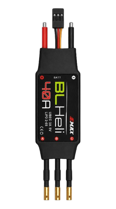
 Design with ESC in Cirkit Designer
Introduction
An Electronic Speed Controller (ESC) is a critical component used to regulate the speed, direction, and braking of an electric motor. It achieves this by adjusting the power supplied to the motor, typically through pulse-width modulation (PWM). ESCs are widely used in remote-controlled (RC) vehicles, drones, electric skateboards, and other applications requiring precise motor control. They are essential for ensuring smooth operation and efficient power delivery in electric propulsion systems.
Explore Projects Built with ESC
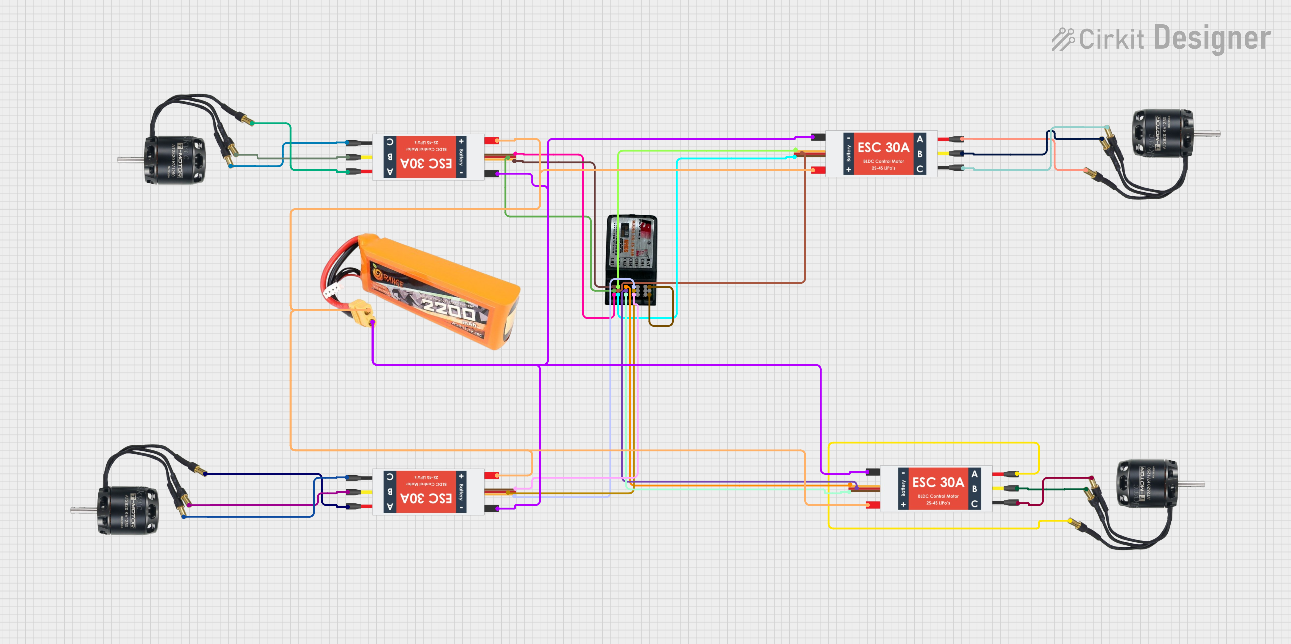 Open Project in Cirkit Designer
 Open Project in Cirkit Designer
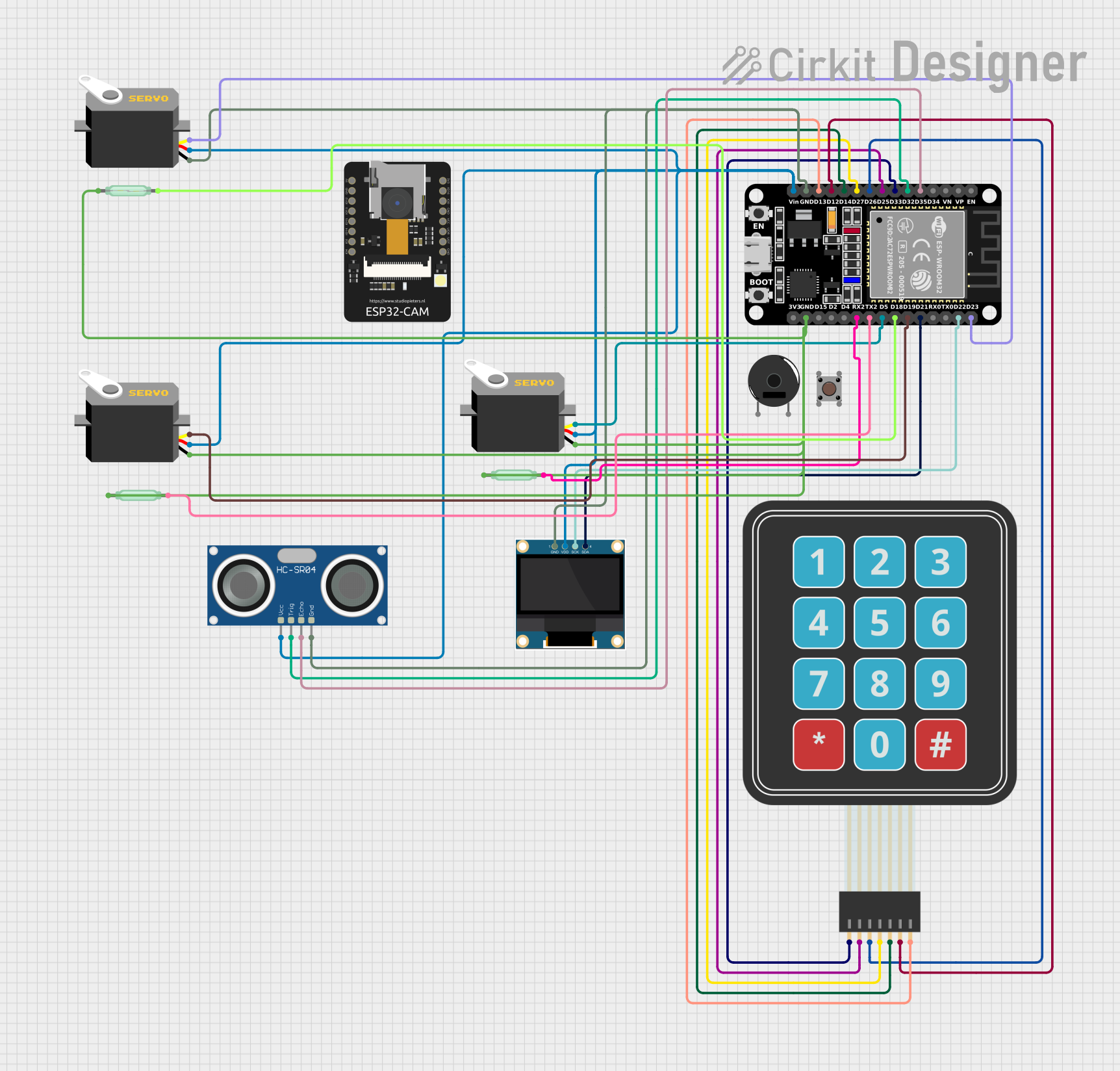 Open Project in Cirkit Designer
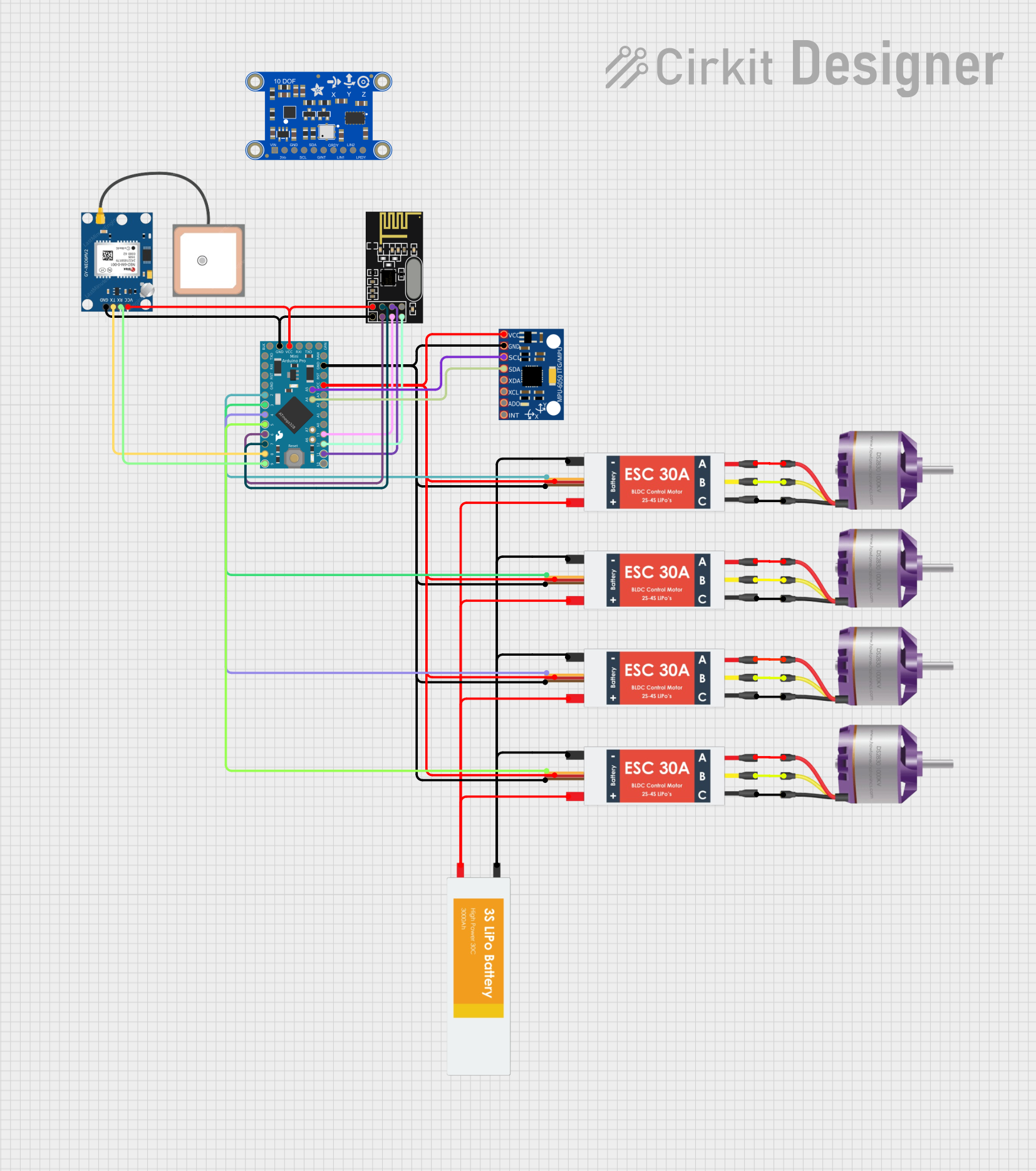 Open Project in Cirkit Designer
Explore Projects Built with ESC
Open Project in Cirkit DesignerOpen Project in Cirkit DesignerOpen Project in Cirkit DesignerOpen Project in Cirkit DesignerCommon Applications
- RC cars, boats, and airplanes
- Multirotor drones (quadcopters, hexacopters, etc.)
- Electric skateboards and scooters
- Robotics and automation systems
- Industrial motor control
Technical Specifications
Below are the general technical specifications of a typical ESC. Note that specific values may vary depending on the model and manufacturer.
Key Technical Details
- Input Voltage Range: 6V to 50V (commonly 2S to 12S LiPo batteries)
- Continuous Current Rating: 10A to 200A (depending on the model)
- Peak Current Rating: Up to 300A (for short durations)
- Supported Motor Types: Brushless DC (BLDC) or Brushed DC motors
- Control Signal Input: PWM (1ms to 2ms pulse width)
- BEC (Battery Eliminator Circuit): 5V or 6V output for powering receivers or microcontrollers (optional)
- Operating Frequency: 8kHz to 32kHz (depending on the ESC firmware)
Pin Configuration and Descriptions
The pin configuration of an ESC typically includes three motor output wires, a power input, and a control signal input. Some ESCs also include a Battery Eliminator Circuit (BEC) output.
| Pin Name | Description |
|---|---|
| Motor Wires (A, B, C) | Connect to the three-phase terminals of a brushless motor. Order determines rotation direction. |
| Power Input (+, -) | Connect to the positive and negative terminals of the battery. Ensure correct polarity. |
| Signal Input (PWM) | Receives control signals (1ms to 2ms pulse width) from a microcontroller or RC receiver. |
| BEC Output (optional) | Provides regulated 5V or 6V power for external devices like receivers or microcontrollers. |
Usage Instructions
How to Use an ESC in a Circuit
- Connect the Motor: Attach the three motor wires (A, B, C) from the ESC to the corresponding terminals on the brushless motor. If the motor spins in the wrong direction, swap any two wires.
- Connect the Power Source: Connect the ESC's power input terminals to the battery. Double-check the polarity to avoid damage.
- Connect the Signal Input: Attach the signal input wire to the PWM output pin of a microcontroller (e.g., Arduino) or an RC receiver.
- Optional BEC Connection: If the ESC includes a BEC, use its output to power your microcontroller or receiver.
- Calibrate the ESC: Many ESCs require calibration to match the throttle range of the controller. Follow the manufacturer's instructions for calibration.
Important Considerations
- Cooling: Ensure proper ventilation or cooling for high-current ESCs to prevent overheating.
- Battery Compatibility: Verify that the ESC's voltage range matches your battery's specifications.
- Firmware Updates: Some ESCs support firmware updates for improved performance or additional features.
- Safety: Always disconnect the battery when making wiring changes to avoid accidental motor activation.
Example: Using an ESC with Arduino UNO
Below is an example of controlling an ESC using an Arduino UNO. The Arduino generates a PWM signal to adjust the motor speed.
#include <Servo.h> // Include the Servo library to generate PWM signals

Servo esc; // Create a Servo object to control the ESC

void setup() {
  esc.attach(9); // Attach the ESC signal wire to pin 9 on the Arduino
  esc.writeMicroseconds(1000); // Set initial throttle to minimum (1000us)
  delay(2000); // Wait for 2 seconds to allow the ESC to initialize
}

void loop() {
  esc.writeMicroseconds(1500); // Set throttle to mid-range (1500us)
  delay(5000); // Run the motor at this speed for 5 seconds

  esc.writeMicroseconds(2000); // Set throttle to maximum (2000us)
  delay(5000); // Run the motor at full speed for 5 seconds

  esc.writeMicroseconds(1000); // Set throttle to minimum (1000us)
  delay(5000); // Stop the motor for 5 seconds
}
Troubleshooting and FAQs
Common Issues and Solutions
Motor Does Not Spin
- Cause: Incorrect wiring or no signal input.
- Solution: Verify motor connections and ensure the ESC is receiving a valid PWM signal.
Motor Spins in the Wrong Direction
- Cause: Incorrect motor wire connections.
- Solution: Swap any two motor wires to reverse the direction.
ESC Overheats
- Cause: Excessive current draw or poor ventilation.
- Solution: Use an ESC with a higher current rating or improve cooling.
ESC Beeps Continuously
- Cause: Calibration required or low battery voltage.
- Solution: Calibrate the ESC and check the battery voltage.
No Power to Receiver or Microcontroller
- Cause: BEC not functioning or not included.
- Solution: Use an external power source if the ESC lacks a BEC.
FAQs
Q: Can I use an ESC with a brushed motor?
A: Only if the ESC is specifically designed for brushed motors. Most ESCs are for brushless motors.Q: How do I know if my ESC supports firmware updates?
A: Check the manufacturer's documentation or website for firmware update compatibility.Q: What happens if I exceed the ESC's voltage or current rating?
A: Exceeding the ratings can damage the ESC or cause it to shut down. Always use an ESC rated for your application.Q: Can I use one ESC to control multiple motors?
A: No, each motor requires its own ESC for independent control.
This concludes the documentation for the Electronic Speed Controller (ESC).