How to Use Step Up Boost Power Converter, Adjustable Voltage Regulator: Examples, Pinouts, and Specs
Introduction
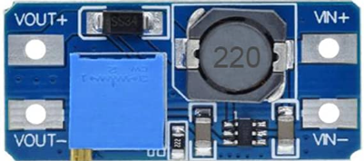
The Youmile Step Up Boost Power Converter is a versatile and efficient adjustable voltage regulator designed to step up a lower input voltage to a higher, stable output voltage. This component is widely used in applications requiring a regulated power supply, such as battery-powered devices, portable electronics, and DIY projects. Its compact design and adjustable output make it ideal for hobbyists and professionals alike.
Common applications include:
- Powering devices requiring a higher voltage than the input source (e.g., USB-powered devices).
- Battery voltage regulation for lithium-ion or alkaline batteries.
- DIY electronics projects and prototyping.
- Solar-powered systems requiring voltage boosting.
Explore Projects Built with Step Up Boost Power Converter, Adjustable Voltage Regulator


Explore Projects Built with Step Up Boost Power Converter, Adjustable Voltage Regulator
Technical Specifications
The following are the key technical details of the Youmile Step Up Boost Power Converter:
| Parameter | Specification |
|---|---|
| Input Voltage Range | 3V to 35V |
| Output Voltage Range | 4V to 40V (adjustable via potentiometer) |
| Maximum Output Current | 2A (continuous), 3A (peak) |
| Conversion Efficiency | Up to 92% (depending on input/output) |
| Switching Frequency | 150 kHz |
| Operating Temperature | -40°C to +85°C |
| Dimensions | 43mm x 21mm x 14mm |
Pin Configuration and Descriptions
The module has four main pins for input and output connections:
| Pin Name | Description |
|---|---|
| VIN+ | Positive input voltage terminal (3V to 35V). |
| VIN- | Negative input voltage terminal (ground). |
| VOUT+ | Positive output voltage terminal (4V to 40V). |
| VOUT- | Negative output voltage terminal (ground). |
Usage Instructions
How to Use the Component in a Circuit
Connect the Input Voltage:
- Connect the positive terminal of your power source to the
VIN+pin. - Connect the negative terminal of your power source to the
VIN-pin.
- Connect the positive terminal of your power source to the
Connect the Output Load:
- Connect the positive terminal of your load to the
VOUT+pin. - Connect the negative terminal of your load to the
VOUT-pin.
- Connect the positive terminal of your load to the
Adjust the Output Voltage:
- Use a small screwdriver to turn the onboard potentiometer.
- Turn clockwise to increase the output voltage or counterclockwise to decrease it.
- Use a multimeter to measure the output voltage while adjusting.
Power On:
- Once all connections are secure, power on the input source.
- Verify the output voltage and ensure it matches your load requirements.
Important Considerations and Best Practices
- Input Voltage Limitations: Ensure the input voltage is within the specified range (3V to 35V). Exceeding this range may damage the module.
- Output Voltage Adjustment: Always measure the output voltage with a multimeter before connecting your load to avoid overvoltage damage.
- Heat Dissipation: For high current applications, ensure proper ventilation or add a heatsink to prevent overheating.
- Polarity Protection: Double-check the polarity of your connections to avoid damaging the module.
Example: Using with an Arduino UNO
The Step Up Boost Power Converter can be used to power an Arduino UNO from a lower voltage source, such as a 3.7V lithium-ion battery. Below is an example setup:
- Connect the battery's positive terminal to
VIN+and negative terminal toVIN-. - Adjust the output voltage to 5V using the potentiometer.
- Connect
VOUT+to the Arduino's 5V pin andVOUT-to the GND pin.
Here is a simple Arduino sketch to verify the setup:
// This sketch blinks the onboard LED to confirm the Arduino is powered
void setup() {
  pinMode(LED_BUILTIN, OUTPUT); // Set the onboard LED pin as output
}

void loop() {
  digitalWrite(LED_BUILTIN, HIGH); // Turn the LED on
  delay(1000);                     // Wait for 1 second
  digitalWrite(LED_BUILTIN, LOW);  // Turn the LED off
  delay(1000);                     // Wait for 1 second
}
Troubleshooting and FAQs
Common Issues and Solutions
No Output Voltage:
- Cause: Incorrect input connections or insufficient input voltage.
- Solution: Verify the input connections and ensure the input voltage is within the specified range.
Output Voltage Not Adjustable:
- Cause: Faulty potentiometer or incorrect adjustment.
- Solution: Ensure the potentiometer is not damaged and adjust it carefully while monitoring with a multimeter.
Overheating:
- Cause: Excessive current draw or poor ventilation.
- Solution: Reduce the load current or add a heatsink to the module.
Load Not Powering On:
- Cause: Output voltage is too low or too high for the load.
- Solution: Measure and adjust the output voltage to match the load's requirements.
FAQs
Q: Can this module step down voltage as well?
A: No, this is a boost converter and can only step up the input voltage. For step-down functionality, use a buck converter.
Q: What happens if I exceed the maximum input voltage?
A: Exceeding the input voltage range (35V) can permanently damage the module. Always stay within the specified range.
Q: Can I use this module with a solar panel?
A: Yes, as long as the solar panel's output voltage is within the input range of the module. Ensure the output voltage is adjusted to match your load.
Q: Is the module protected against reverse polarity?
A: No, the module does not have built-in reverse polarity protection. Double-check your connections before powering on.
By following this documentation, you can effectively use the Youmile Step Up Boost Power Converter in your projects.