Cirkit Designer Logo
Cirkit Designer
Your all-in-one circuit design IDE
Home / 
Component Documentation

How to Use Itsy Bitsy 32u4 5V @ 16MHz: Examples, Pinouts, and Specs

Image of Itsy Bitsy 32u4 5V @ 16MHz
Cirkit Designer LogoDesign with Itsy Bitsy 32u4 5V @ 16MHz in Cirkit Designer

Introduction

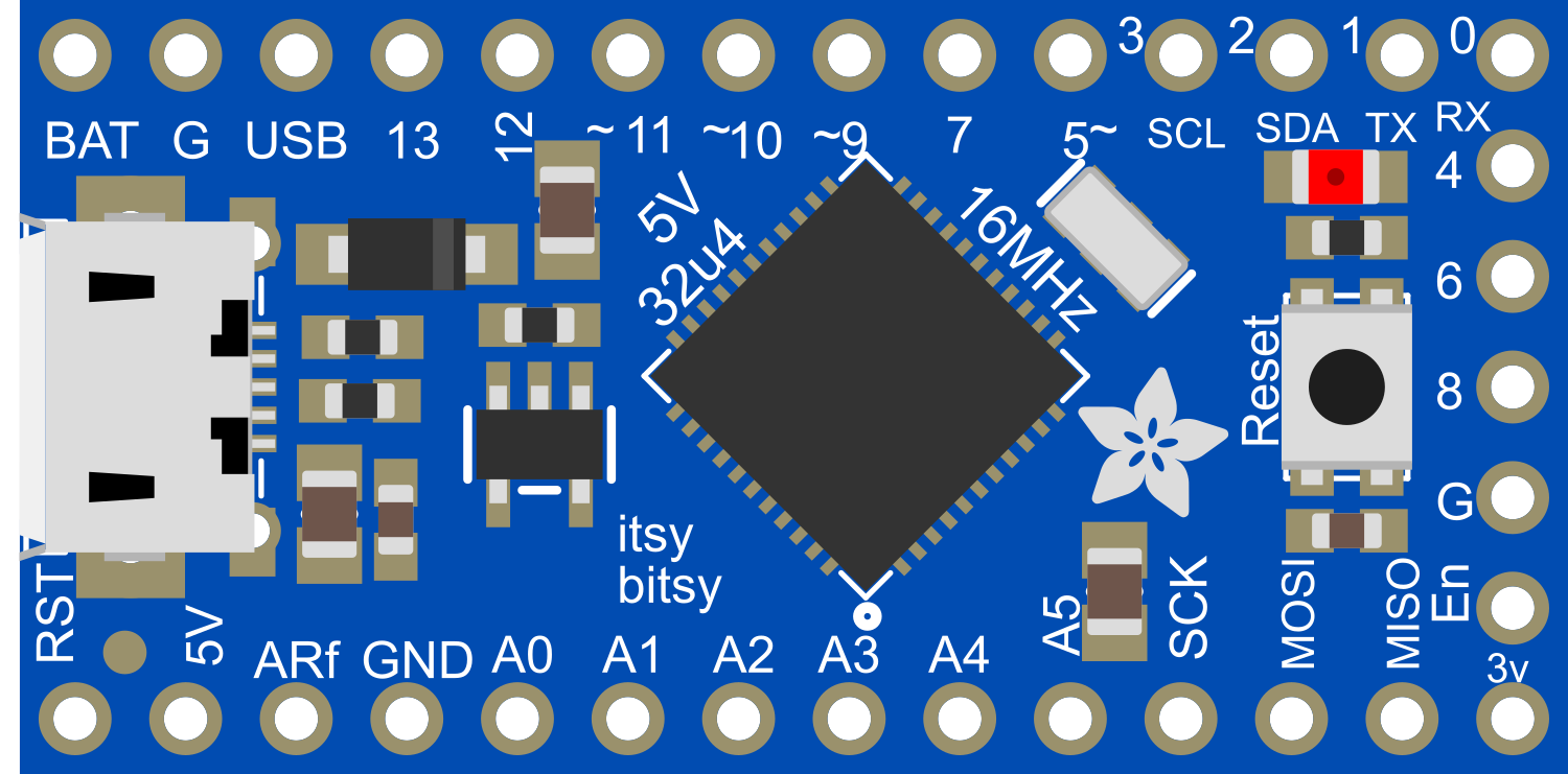
The Itsy Bitsy 32u4 5V @ 16MHz is a compact, Arduino-compatible microcontroller board powered by the ATmega32u4 chip. It is designed for small projects where space is at a premium, without compromising on processing power and functionality. This board operates at 5V and a clock speed of 16MHz, which is the same as the Arduino Leonardo and Micro, making it suitable for a wide range of applications including wearables, portable instruments, and custom USB peripherals.

Explore Projects Built with Itsy Bitsy 32u4 5V @ 16MHz

Use Cirkit Designer to design, explore, and prototype these projects online. Some projects support real-time simulation. Click "Open Project" to start designing instantly!
Itsy Bitsy M0 Express Controlled Quad Servo Circuit
Image of LOCO: A project utilizing Itsy Bitsy 32u4 5V @ 16MHz in a practical application
This circuit consists of an Itsy Bitsy M0 Express microcontroller connected to four Tower Pro SG90 servos. Each servo is controlled by a distinct digital output pin (D7, D9, D10, D11) from the microcontroller. The servos share a common ground with the microcontroller and are powered by a 5V battery connected to their power inputs.
Cirkit Designer LogoOpen Project in Cirkit Designer
Itsy Bitsy M0 Express Controlled Multi-Servo System
Image of Crab Robot Circuit: A project utilizing Itsy Bitsy 32u4 5V @ 16MHz in a practical application
This circuit consists of an Itsy Bitsy M0 Express microcontroller connected to eight Tower Pro SG90 servos. Each servo is controlled by a different digital or analog output pin on the microcontroller. A single power supply provides +5V and GND to all servos, and the microcontroller is configured with some of its pins interconnected for potential programming or operational purposes.
Cirkit Designer LogoOpen Project in Cirkit Designer
ESP32-S3 Based Vibration Detection System with TFT Display and Power Backup
Image of IOT Thesis: A project utilizing Itsy Bitsy 32u4 5V @ 16MHz in a practical application
This circuit features an ESP32-S3 microcontroller connected to various peripherals including an ADXL355 accelerometer, an SW-420 vibration sensor, a buzzer module, and an ILI9341 TFT display. The ESP32-S3 manages sensor inputs and provides output to the display and buzzer. Power management is handled by a 12V to 5V step-down converter, and a UPS ensures uninterrupted power supply, with a rocker switch to control the power flow.
Cirkit Designer LogoOpen Project in Cirkit Designer
ATmega328P-Based Sensor Hub with OLED Display and LIDAR
Image of TILTPCB: A project utilizing Itsy Bitsy 32u4 5V @ 16MHz in a practical application
This circuit features an Mtiny Uno ATmega328P microcontroller as its central processing unit, interfacing with a variety of sensors and peripherals. It includes a 0.96" OLED display and an MPU6050 accelerometer/gyroscope for user interface and motion sensing, respectively. The circuit also integrates a TF LUNA LIDAR for distance measurement, a DHT11 sensor for temperature and humidity readings, and uses a 9V battery with a 7805 voltage regulator for power management. Communication with a computer for programming and data exchange is facilitated by an Adafruit FTDI Friend module.
Cirkit Designer LogoOpen Project in Cirkit Designer

Explore Projects Built with Itsy Bitsy 32u4 5V @ 16MHz

Use Cirkit Designer to design, explore, and prototype these projects online. Some projects support real-time simulation. Click "Open Project" to start designing instantly!
Image of LOCO: A project utilizing Itsy Bitsy 32u4 5V @ 16MHz in a practical application
Itsy Bitsy M0 Express Controlled Quad Servo Circuit
This circuit consists of an Itsy Bitsy M0 Express microcontroller connected to four Tower Pro SG90 servos. Each servo is controlled by a distinct digital output pin (D7, D9, D10, D11) from the microcontroller. The servos share a common ground with the microcontroller and are powered by a 5V battery connected to their power inputs.
Cirkit Designer LogoOpen Project in Cirkit Designer
Image of Crab Robot Circuit: A project utilizing Itsy Bitsy 32u4 5V @ 16MHz in a practical application
Itsy Bitsy M0 Express Controlled Multi-Servo System
This circuit consists of an Itsy Bitsy M0 Express microcontroller connected to eight Tower Pro SG90 servos. Each servo is controlled by a different digital or analog output pin on the microcontroller. A single power supply provides +5V and GND to all servos, and the microcontroller is configured with some of its pins interconnected for potential programming or operational purposes.
Cirkit Designer LogoOpen Project in Cirkit Designer
Image of IOT Thesis: A project utilizing Itsy Bitsy 32u4 5V @ 16MHz in a practical application
ESP32-S3 Based Vibration Detection System with TFT Display and Power Backup
This circuit features an ESP32-S3 microcontroller connected to various peripherals including an ADXL355 accelerometer, an SW-420 vibration sensor, a buzzer module, and an ILI9341 TFT display. The ESP32-S3 manages sensor inputs and provides output to the display and buzzer. Power management is handled by a 12V to 5V step-down converter, and a UPS ensures uninterrupted power supply, with a rocker switch to control the power flow.
Cirkit Designer LogoOpen Project in Cirkit Designer
Image of TILTPCB: A project utilizing Itsy Bitsy 32u4 5V @ 16MHz in a practical application
ATmega328P-Based Sensor Hub with OLED Display and LIDAR
This circuit features an Mtiny Uno ATmega328P microcontroller as its central processing unit, interfacing with a variety of sensors and peripherals. It includes a 0.96" OLED display and an MPU6050 accelerometer/gyroscope for user interface and motion sensing, respectively. The circuit also integrates a TF LUNA LIDAR for distance measurement, a DHT11 sensor for temperature and humidity readings, and uses a 9V battery with a 7805 voltage regulator for power management. Communication with a computer for programming and data exchange is facilitated by an Adafruit FTDI Friend module.
Cirkit Designer LogoOpen Project in Cirkit Designer

Common Applications and Use Cases

  • DIY electronics projects
  • Wearable devices
  • USB HID devices (keyboards, mice, game controllers)
  • Prototyping IoT devices
  • Educational purposes and learning embedded systems

Technical Specifications

Key Technical Details

  • Microcontroller: ATmega32u4
  • Operating Voltage: 5V
  • Input Voltage: 6-16V
  • Digital I/O Pins: 23
  • PWM Channels: 7
  • Analog Input Channels: 12
  • DC Current per I/O Pin: 40 mA
  • DC Current for 3.3V Pin: 50 mA
  • Flash Memory: 32 KB (ATmega32u4) of which 4 KB used by bootloader
  • SRAM: 2.5 KB (ATmega32u4)
  • EEPROM: 1 KB (ATmega32u4)
  • Clock Speed: 16 MHz

Pin Configuration and Descriptions

Pin Number Function Description
1 GND Ground
2 VIN Voltage input for the board
3-7 Digital Pins Digital input/output pins, PWM capable
8-9 Analog Pins Analog input pins
10 RESET Reset pin, active low
11-17 Digital Pins Digital input/output pins, PWM capable
18-23 Analog Pins Analog input pins, also digital I/O capable
24 5V Regulated 5V output
25 3.3V Regulated 3.3V output
26 AREF Analog reference voltage for the ADC
27 SCK Serial Clock for SPI communication
28 MISO Master In Slave Out for SPI communication
29 MOSI Master Out Slave In for SPI communication
30 RXLED LED indicating USB data reception
31 TXLED LED indicating USB data transmission
32 SDA Data line for I2C communication
33 SCL Clock line for I2C communication

Usage Instructions

How to Use the Component in a Circuit

  1. Powering the Board: Connect a power supply to the VIN pin (6-16V) or plug the board into a USB port for power.
  2. Programming: Use the micro USB port to connect the Itsy Bitsy to a computer for programming via the Arduino IDE.
  3. Digital I/O: Utilize the digital pins for input or output functions. Remember to set the pin mode in your code.
  4. Analog Input: Connect sensors to the analog pins to read varying voltages.
  5. PWM Output: Use PWM-capable pins to control devices like LEDs or motors with analog-like behavior.
  6. Serial Communication: Utilize RX and TX pins for serial communication.
  7. I2C and SPI: Use dedicated pins for I2C or SPI communication with peripherals.

Important Considerations and Best Practices

  • Always ensure that the power supply voltage does not exceed the recommended range to prevent damage to the board.
  • When connecting external components, make sure they are compatible with the board's logic level (5V).
  • Avoid drawing more current than the maximum specified for each pin and for the board overall.
  • Use a current limiting resistor when connecting LEDs directly to the output pins.
  • Disconnect the board from power sources before making or altering connections to prevent shorts or component damage.

Troubleshooting and FAQs

Common Issues Users Might Face

  • Board not recognized by computer: Ensure the micro USB cable is data-capable and the board's drivers are installed.
  • Sketch not uploading: Check the selected board and port in the Arduino IDE, and ensure the bootloader is not corrupted.
  • Incorrect behavior of I/O pins: Verify that the pin modes and states are correctly set in your sketch.

Solutions and Tips for Troubleshooting

  • If the board is not recognized, try a different USB cable or port, and reset the board.
  • For upload issues, double-check the connections, select the correct board from the Tools menu, and ensure the correct drivers are installed.
  • Review your code for any logical errors or incorrect pin assignments that could cause unexpected behavior.

FAQs

Q: Can I use the Itsy Bitsy 32u4 with Arduino shields? A: Due to its small size, it may not be directly compatible with many shields designed for larger Arduino boards. However, with appropriate wiring, you can connect shield components to the Itsy Bitsy.

Q: How do I reset the board? A: Briefly connect the RESET pin to GND or press the reset button if available.

Q: What is the maximum current the board can supply? A: The board can supply up to 40 mA per I/O pin, with a maximum of 50 mA for the 3.3V pin.

Example Code for Arduino UNO

// Blink an LED connected to pin 13
void setup() {
  pinMode(13, OUTPUT); // Set pin 13 as an output
}

void loop() {
  digitalWrite(13, HIGH); // Turn the LED on
  delay(1000);           // Wait for a second
  digitalWrite(13, LOW);  // Turn the LED off
  delay(1000);           // Wait for a second
}

Note: The example code provided is for the Arduino UNO but is also compatible with the Itsy Bitsy 32u4 5V @ 16MHz, as they share the same microcontroller and similar pinout structure.