
How to Use Scart Houseing: Examples, Pinouts, and Specs
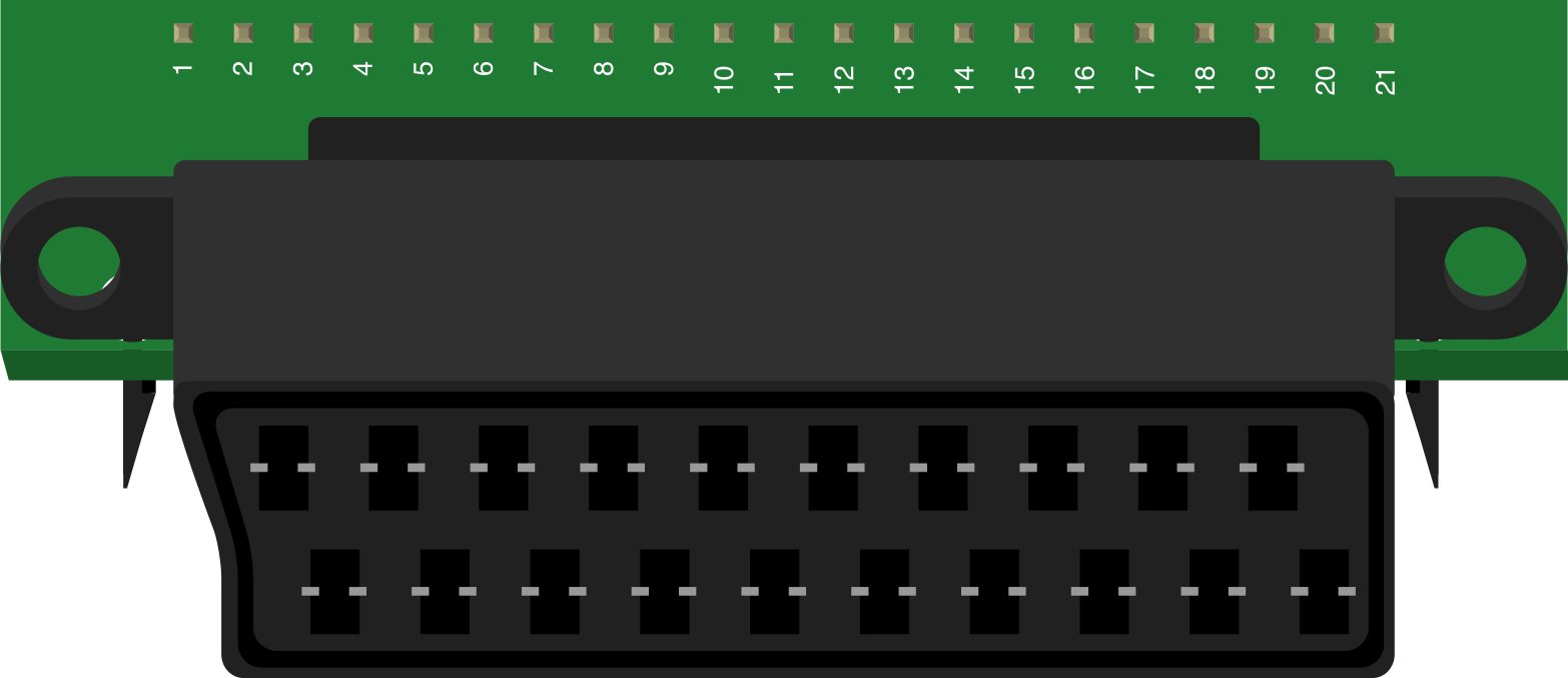
 Design with Scart Houseing in Cirkit Designer
Introduction
The SCART Housing is a connector housing designed to accommodate SCART connectors, which are widely used in audio and video equipment. This housing provides a secure and organized interface for connecting devices, ensuring reliable signal transmission and physical durability. SCART connectors are commonly found in older televisions, DVD players, and gaming consoles, making the SCART Housing an essential component for maintaining and repairing legacy AV systems.
Explore Projects Built with Scart Houseing
 Open Project in Cirkit Designer
 Open Project in Cirkit Designer
 Open Project in Cirkit Designer
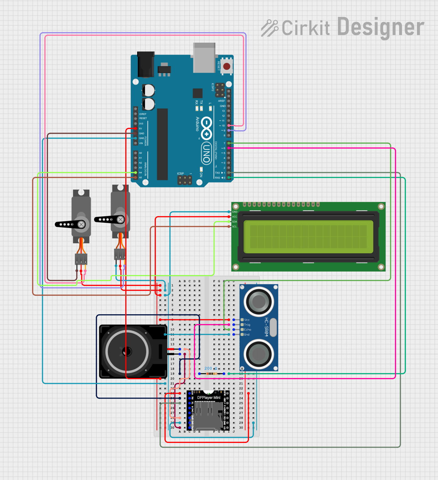 Open Project in Cirkit Designer
Explore Projects Built with Scart Houseing
Open Project in Cirkit DesignerOpen Project in Cirkit DesignerOpen Project in Cirkit DesignerOpen Project in Cirkit DesignerCommon Applications and Use Cases
- Connecting audio and video equipment such as TVs, VCRs, and DVD players.
- Repairing or replacing damaged SCART connectors in legacy systems.
- Organizing and securing SCART connections in custom AV setups.
- Prototyping or testing SCART-based circuits in electronics projects.
Technical Specifications
Key Technical Details
- Material: High-quality ABS plastic or metal (varies by model).
- Compatibility: Standard 21-pin SCART connectors.
- Dimensions: Typically 50mm x 20mm x 40mm (may vary by manufacturer).
- Mounting Options: Snap-fit or screw-secured design.
- Temperature Range: -20°C to 70°C.
- Durability: Resistant to wear and tear from repeated connections.
Pin Configuration and Descriptions
The SCART Housing itself does not alter the pin configuration of the SCART connector it houses. Below is the standard SCART pinout for reference:
| Pin Number | Signal Name | Description |
|---|---|---|
| 1 | Audio Out (Right) | Right audio channel output. |
| 2 | Audio In (Right) | Right audio channel input. |
| 3 | Audio Out (Left/Mono) | Left audio channel or mono output. |
| 4 | Audio Ground | Ground for audio signals. |
| 5 | Blue Ground | Ground for blue video signal. |
| 6 | Audio In (Left/Mono) | Left audio channel or mono input. |
| 7 | Blue In | Blue video signal input. |
| 8 | Function Switching | Signal to switch TV input mode. |
| 9 | Green Ground | Ground for green video signal. |
| 10 | Clock Out | Data clock output (optional). |
| 11 | Green In | Green video signal input. |
| 12 | Reserved | Reserved for future use. |
| 13 | Red Ground | Ground for red video signal. |
| 14 | Data Ground | Ground for data signals. |
| 15 | Red In | Red video signal input. |
| 16 | Blanking Signal | Signal for RGB switching. |
| 17 | Video Ground | Ground for composite video signal. |
| 18 | Blanking Ground | Ground for blanking signal. |
| 19 | Video Out | Composite video output. |
| 20 | Video In | Composite video input. |
| 21 | Shield | Overall shield ground. |
Usage Instructions
How to Use the SCART Housing in a Circuit
- Prepare the SCART Connector: Ensure the SCART connector is properly wired according to the standard pinout.
- Insert the Connector: Slide the SCART connector into the housing, aligning it with the internal guides.
- Secure the Housing: Depending on the model, snap the housing shut or secure it with screws.
- Connect to Devices: Plug the SCART connector into the corresponding port on your audio or video equipment.
- Test the Connection: Verify that the audio and video signals are transmitted correctly.
Important Considerations and Best Practices
- Cable Strain Relief: Use the built-in strain relief features of the housing to prevent cable damage.
- Compatibility Check: Ensure the housing is compatible with your SCART connector and equipment.
- Avoid Over-Tightening: If the housing uses screws, avoid over-tightening to prevent damage to the housing or connector.
- Signal Quality: Use high-quality cables and connectors to minimize signal degradation.
Example: Connecting to an Arduino UNO
While SCART Housings are not directly used with microcontrollers like the Arduino UNO, you can use the SCART connector for AV signal processing in projects. Below is an example of how to send a simple composite video signal using an Arduino:
/*
  Simple Composite Video Signal Generator
  This code generates a basic video signal for testing SCART connections.
  Connect the Arduino's output pin to the SCART Video In pin (Pin 20).
*/

const int videoPin = 9; // Pin connected to SCART Video In (Pin 20)

void setup() {
  pinMode(videoPin, OUTPUT);
}

void loop() {
  // Generate a simple square wave for testing
  digitalWrite(videoPin, HIGH);
  delayMicroseconds(64); // High for 64 microseconds
  digitalWrite(videoPin, LOW);
  delayMicroseconds(64); // Low for 64 microseconds
}
Note: This example is for testing purposes only and does not generate a valid video signal for display devices.
Troubleshooting and FAQs
Common Issues Users Might Face
- Loose Connection: The SCART connector may not fit securely in the housing.
- Solution: Ensure the connector is properly aligned and fully inserted into the housing.
- Signal Degradation: Poor audio or video quality.
- Solution: Check for damaged cables or connectors and ensure proper grounding.
- Housing Does Not Close: The housing may not snap or screw shut.
- Solution: Verify that the connector and cables are properly seated and not obstructing the housing.
Solutions and Tips for Troubleshooting
- Inspect the Housing: Look for any physical damage or debris inside the housing.
- Test with Known Good Equipment: Use a working SCART cable and device to isolate the issue.
- Check Pinout: Ensure the SCART connector is wired correctly according to the standard pinout.
By following this documentation, you can effectively use the SCART Housing to maintain and enhance your audio and video equipment connections.