How to Use Encoder Metal Gearmotor 12V DC High Speed 300RPM: Examples, Pinouts, and Specs

Introduction
The Encoder Metal Gearmotor 12V DC High Speed 300RPM by Bemonoc is a high-performance gearmotor designed for applications requiring both speed and precision. This motor operates at 12V DC and delivers a rotational speed of 300 RPM, making it suitable for robotics, automation, and other motion control systems. The integrated encoder provides precise position and speed feedback, enabling closed-loop control for enhanced accuracy.
Explore Projects Built with Encoder Metal Gearmotor 12V DC High Speed 300RPM
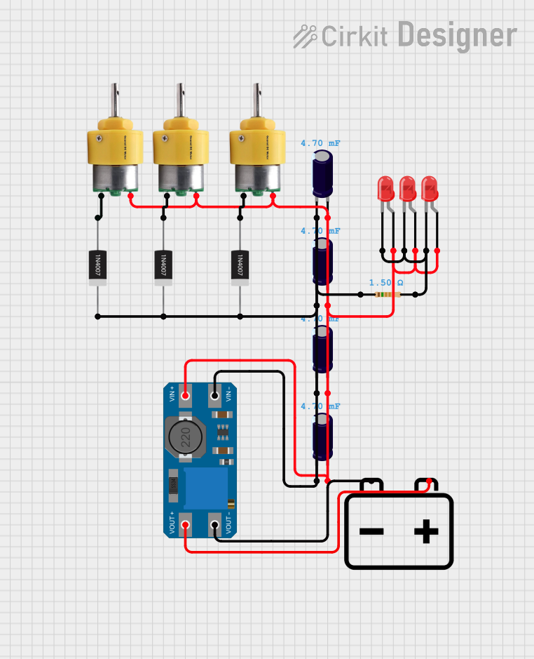

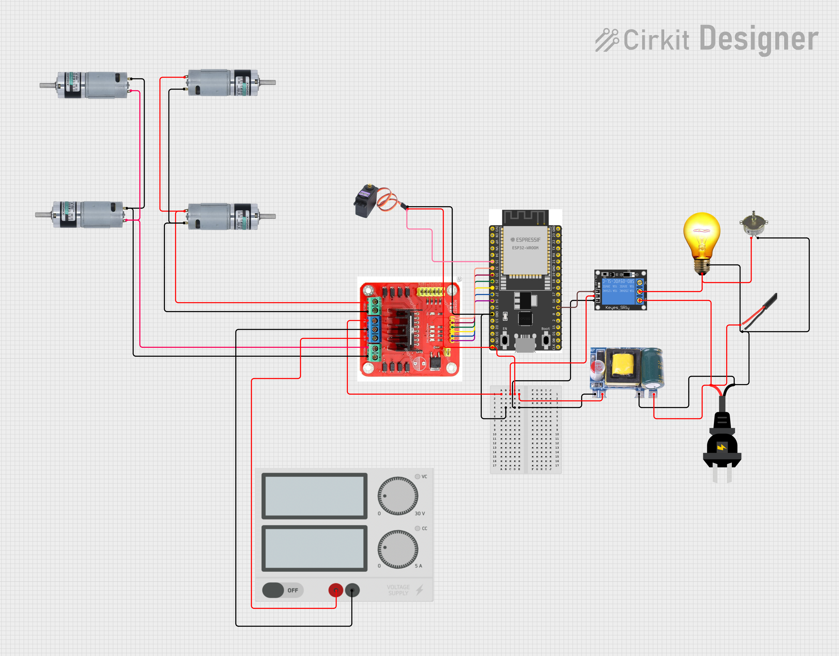
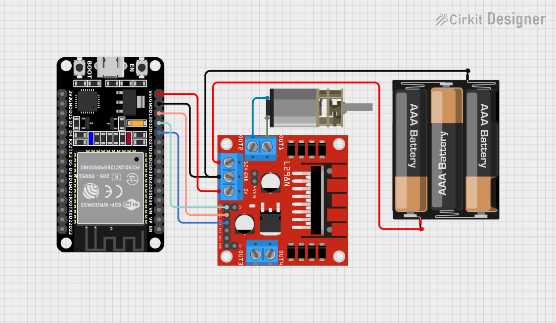
Explore Projects Built with Encoder Metal Gearmotor 12V DC High Speed 300RPM
Common Applications
- Robotics (e.g., mobile robots, robotic arms)
- Conveyor systems
- Automated guided vehicles (AGVs)
- CNC machines and 3D printers
- Precision motion control in industrial automation
Technical Specifications
Below are the key technical details of the Encoder Metal Gearmotor:
| Parameter | Value |
|---|---|
| Operating Voltage | 12V DC |
| No-Load Speed | 300 RPM |
| Rated Torque | 1.2 kg·cm |
| Stall Torque | 6.0 kg·cm |
| Gear Ratio | 1:34 |
| Encoder Resolution | 11 pulses per revolution |
| Shaft Diameter | 6 mm |
| Motor Dimensions | 70 mm x 32 mm x 32 mm |
| Weight | 200 g |
Pin Configuration and Descriptions
The motor comes with a 6-pin connector for power and encoder signals. The pinout is as follows:
| Pin | Name | Description |
|---|---|---|
| 1 | Motor+ | Positive terminal for motor power (12V DC) |
| 2 | Motor- | Negative terminal for motor power (GND) |
| 3 | Encoder VCC | Power supply for the encoder (5V DC) |
| 4 | Encoder GND | Ground for the encoder |
| 5 | Encoder A | Encoder channel A output (quadrature signal) |
| 6 | Encoder B | Encoder channel B output (quadrature signal) |
Usage Instructions
How to Use the Component in a Circuit
- Powering the Motor: Connect the
Motor+andMotor-pins to a 12V DC power source. Ensure the power supply can handle the motor's current requirements. - Connecting the Encoder:
- Provide a 5V DC supply to the
Encoder VCCpin and connect theEncoder GNDpin to ground. - Connect the
Encoder AandEncoder Bpins to a microcontroller or motor driver capable of reading quadrature signals.
- Provide a 5V DC supply to the
- Controlling the Motor: Use an H-bridge motor driver to control the motor's speed and direction. The encoder signals can be used for closed-loop control.
Important Considerations and Best Practices
- Power Supply: Ensure the power supply can deliver sufficient current to avoid voltage drops or motor stalling.
- Heat Dissipation: The motor may heat up during prolonged use. Allow adequate ventilation or use a heat sink if necessary.
- Encoder Signal Handling: Use pull-up resistors on the encoder pins if required by your microcontroller.
- Noise Filtering: Add capacitors across the motor terminals to reduce electrical noise that may interfere with the encoder signals.
Example: Using with Arduino UNO
Below is an example of how to interface the motor and encoder with an Arduino UNO for speed measurement:
// Define encoder pins
const int encoderA = 2;  // Encoder channel A connected to digital pin 2
const int encoderB = 3;  // Encoder channel B connected to digital pin 3

volatile int encoderCount = 0;  // Variable to store encoder counts

// Interrupt service routine for encoder channel A
void encoderISR() {
  // Check the direction of rotation using channel B
  if (digitalRead(encoderB) == HIGH) {
    encoderCount++;  // Clockwise rotation
  } else {
    encoderCount--;  // Counterclockwise rotation
  }
}

void setup() {
  // Initialize serial communication
  Serial.begin(9600);

  // Configure encoder pins as inputs
  pinMode(encoderA, INPUT);
  pinMode(encoderB, INPUT);

  // Attach interrupt to encoder channel A
  attachInterrupt(digitalPinToInterrupt(encoderA), encoderISR, RISING);

  Serial.println("Encoder initialized.");
}

void loop() {
  // Print the encoder count to the serial monitor
  Serial.print("Encoder Count: ");
  Serial.println(encoderCount);

  delay(100);  // Delay for readability
}
Notes:
- Ensure the encoder pins are connected to interrupt-capable pins on the Arduino (e.g., pins 2 and 3 on the UNO).
- Use a motor driver (e.g., L298N or TB6612FNG) to control the motor's speed and direction.
Troubleshooting and FAQs
Common Issues and Solutions
Motor Does Not Spin:
- Check the power supply voltage and current rating.
- Verify the connections to the
Motor+andMotor-pins. - Ensure the motor driver is functioning correctly.
Encoder Signals Are Unstable:
- Add pull-up resistors to the encoder pins if the signals are floating.
- Use capacitors across the motor terminals to reduce electrical noise.
- Ensure proper grounding between the motor, encoder, and microcontroller.
Motor Overheats:
- Reduce the load on the motor or limit the operating time.
- Ensure adequate ventilation or use a heat sink.
Incorrect Encoder Readings:
- Verify the encoder pin connections.
- Check the interrupt configuration in the microcontroller code.
- Ensure the encoder power supply is stable at 5V DC.
FAQs
Q1: Can this motor be powered with a voltage other than 12V?
A1: While the motor may operate at lower voltages, its performance (speed and torque) will be reduced. Operating above 12V is not recommended as it may damage the motor.
Q2: What is the purpose of the encoder?
A2: The encoder provides feedback on the motor's position and speed, enabling precise control in applications like robotics and automation.
Q3: Can I use this motor without the encoder?
A3: Yes, the motor can be used without the encoder for simple applications, but you will lose the ability to monitor and control its position and speed accurately.
Q4: What type of motor driver is recommended?
A4: An H-bridge motor driver like the L298N or TB6612FNG is recommended for controlling this motor.
By following this documentation, you can effectively integrate the Encoder Metal Gearmotor 12V DC High Speed 300RPM into your projects for reliable and precise motion control.