Cirkit Designer Logo
Cirkit Designer
Your all-in-one circuit design IDE
Home / 
Component Documentation

How to Use doppler radar: Examples, Pinouts, and Specs

Image of doppler radar
Cirkit Designer LogoDesign with doppler radar in Cirkit Designer

Introduction

A Doppler radar module is an electronic device that employs the Doppler effect to determine the velocity of an object. It emits microwave signals and then receives the reflected waves from a moving target. The frequency shift between the emitted and received signals is used to calculate the velocity of the object. Doppler radar modules are commonly used in speed detection, motion sensors, and automatic door openers.

Explore Projects Built with doppler radar

Use Cirkit Designer to design, explore, and prototype these projects online. Some projects support real-time simulation. Click "Open Project" to start designing instantly!
Arduino-Based Doppler Radar with RF Transmission and LCD Display
Image of Doppler Radar: A project utilizing doppler radar in a practical application
This circuit features an Arduino UNO microcontroller interfaced with an RF 433 MHz Transmitter, a Transmitter RF Module, an LCD screen with I2C communication, and a doppler radar sensor. The Arduino controls the RF transmission and processes the doppler radar's signal, likely for motion detection purposes. The LCD screen is used to display information or statuses, and the RF modules enable wireless communication, possibly to transmit the processed radar data.
Cirkit Designer LogoOpen Project in Cirkit Designer
Arduino UNO Based Ultrasonic Radar System with Servo Motor
Image of ultrasonic radar: A project utilizing doppler radar in a practical application
This circuit is designed to function as an ultrasonic radar system, utilizing an Arduino UNO microcontroller, an HC-SR04 ultrasonic sensor, and an SG90 servo motor. The Arduino controls the servo to sweep the ultrasonic sensor through a range of angles, while the sensor measures the distance to any objects in its path. The system outputs the angle and distance measurements to the serial monitor and provides an indication when an obstacle is detected within 20 cm.
Cirkit Designer LogoOpen Project in Cirkit Designer
Raspberry Pi 4B and MMWave Radar Sensor-Based Smart LED Indicator
Image of Capstone Connections: A project utilizing doppler radar in a practical application
This circuit integrates a Raspberry Pi 4B with an MMWave radar sensor and two LEDs (red and green). The Raspberry Pi powers and communicates with the radar sensor via GPIO pins, and controls the LEDs to indicate the status or results of the radar sensor's operation.
Cirkit Designer LogoOpen Project in Cirkit Designer
ESP32-CAM and Arduino Nano Radiation Detection System with GPS and Wi-Fi Connectivity
Image of esp32camGps: A project utilizing doppler radar in a practical application
This circuit is a radiation detection and monitoring system that uses an ESP32-CAM for capturing images and streaming video, an Arduino Nano for processing data from a GPS module and a Geiger counter, and a bi-directional logic level converter for interfacing between different voltage levels. The ESP32-CAM also serves as a web server to display the radiation levels and GPS coordinates in real-time.
Cirkit Designer LogoOpen Project in Cirkit Designer

Explore Projects Built with doppler radar

Use Cirkit Designer to design, explore, and prototype these projects online. Some projects support real-time simulation. Click "Open Project" to start designing instantly!
Image of Doppler Radar: A project utilizing doppler radar in a practical application
Arduino-Based Doppler Radar with RF Transmission and LCD Display
This circuit features an Arduino UNO microcontroller interfaced with an RF 433 MHz Transmitter, a Transmitter RF Module, an LCD screen with I2C communication, and a doppler radar sensor. The Arduino controls the RF transmission and processes the doppler radar's signal, likely for motion detection purposes. The LCD screen is used to display information or statuses, and the RF modules enable wireless communication, possibly to transmit the processed radar data.
Cirkit Designer LogoOpen Project in Cirkit Designer
Image of ultrasonic radar: A project utilizing doppler radar in a practical application
Arduino UNO Based Ultrasonic Radar System with Servo Motor
This circuit is designed to function as an ultrasonic radar system, utilizing an Arduino UNO microcontroller, an HC-SR04 ultrasonic sensor, and an SG90 servo motor. The Arduino controls the servo to sweep the ultrasonic sensor through a range of angles, while the sensor measures the distance to any objects in its path. The system outputs the angle and distance measurements to the serial monitor and provides an indication when an obstacle is detected within 20 cm.
Cirkit Designer LogoOpen Project in Cirkit Designer
Image of Capstone Connections: A project utilizing doppler radar in a practical application
Raspberry Pi 4B and MMWave Radar Sensor-Based Smart LED Indicator
This circuit integrates a Raspberry Pi 4B with an MMWave radar sensor and two LEDs (red and green). The Raspberry Pi powers and communicates with the radar sensor via GPIO pins, and controls the LEDs to indicate the status or results of the radar sensor's operation.
Cirkit Designer LogoOpen Project in Cirkit Designer
Image of esp32camGps: A project utilizing doppler radar in a practical application
ESP32-CAM and Arduino Nano Radiation Detection System with GPS and Wi-Fi Connectivity
This circuit is a radiation detection and monitoring system that uses an ESP32-CAM for capturing images and streaming video, an Arduino Nano for processing data from a GPS module and a Geiger counter, and a bi-directional logic level converter for interfacing between different voltage levels. The ESP32-CAM also serves as a web server to display the radiation levels and GPS coordinates in real-time.
Cirkit Designer LogoOpen Project in Cirkit Designer

Common Applications and Use Cases

  • Traffic speed monitoring
  • Automatic door sensors
  • Intruder detection systems
  • Robotics for obstacle avoidance
  • Home automation for presence detection

Technical Specifications

Key Technical Details

  • Operating Frequency: Typically in the microwave range, e.g., 10.525 GHz
  • Output Power: Usually in the milliwatt range, e.g., 5mW
  • Detection Range: Varies by model, e.g., 2 to 20 meters
  • Voltage Supply Range: 4.5V to 5.5V DC
  • Current Consumption: 30mA to 100mA depending on the model

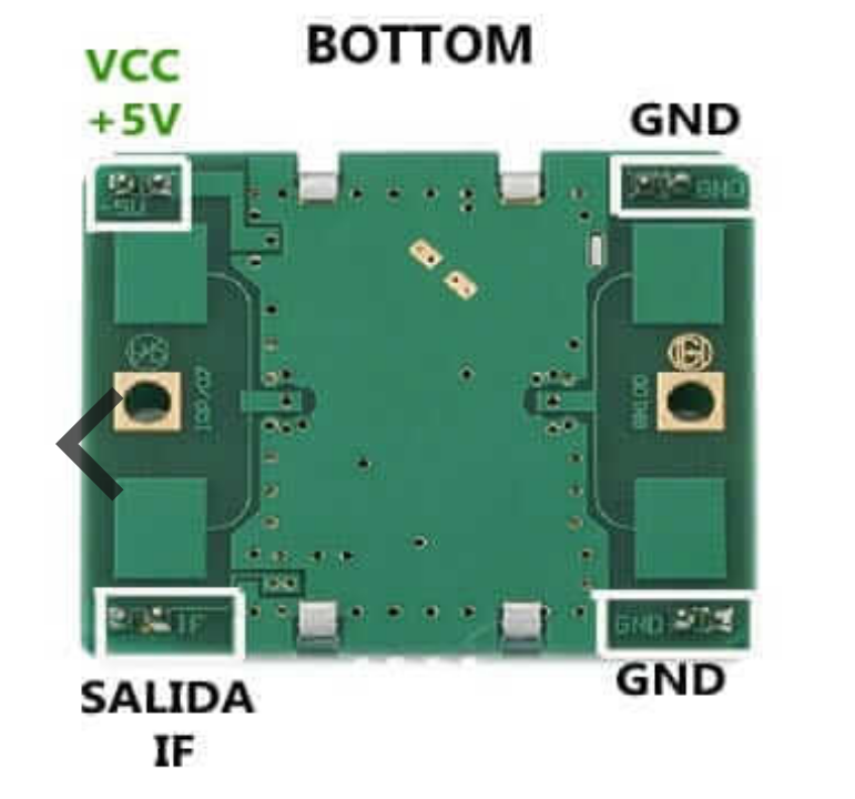
Pin Configuration and Descriptions

Pin Number Name Description
1 Vcc Power supply input (4.5V to 5.5V DC)
2 GND Ground connection
3 OUT Output signal (digital or analog, depending on the model)
4 CDS Light-dependent resistor (LDR) input for controlling sensitivity based on ambient light (optional, not present on all models)

Usage Instructions

How to Use the Component in a Circuit

  1. Power Supply: Connect the Vcc pin to a suitable power source within the specified voltage range and the GND pin to the ground of the power supply.
  2. Output Signal: Connect the OUT pin to a digital input pin on a microcontroller if the output is digital, or to an analog input if the output is analog.
  3. Ambient Light Sensitivity (Optional): If available, connect a photoresistor to the CDS pin to enable automatic adjustment of the radar sensitivity based on ambient light conditions.

Important Considerations and Best Practices

  • Ensure that the power supply does not exceed the recommended voltage range to prevent damage to the module.
  • Place the module in a position where it has a clear line of sight to the area of interest for accurate detection.
  • Avoid placing objects too close to the radar module as it may cause false triggers or interfere with the signal.
  • Use appropriate decoupling capacitors close to the module's power supply pins to minimize power supply noise.

Example Arduino Code

// Define the pin connected to the Doppler radar module's output
const int radarPin = 2;

void setup() {
  // Initialize the radarPin as an input
  pinMode(radarPin, INPUT);
  // Begin serial communication at 9600 baud rate
  Serial.begin(9600);
}

void loop() {
  // Read the state of the radar's output
  int radarState = digitalRead(radarPin);
  
  // If the output is HIGH, motion is detected
  if (radarState == HIGH) {
    Serial.println("Motion detected!");
  } else {
    Serial.println("No motion detected.");
  }
  
  // Wait for a short period before reading again
  delay(100);
}

Troubleshooting and FAQs

Common Issues Users Might Face

  • No Output Signal: Ensure that the module is correctly powered and that the pins are properly connected. Check for any loose connections.
  • False Triggers: Adjust the module's placement or consider adding a delay in the code to filter out short, unintended triggers.
  • Inconsistent Detection: Make sure that the module is not obstructed and that it has a clear line of sight to the target area.

Solutions and Tips for Troubleshooting

  • Verify the power supply voltage with a multimeter to ensure it is within the specified range.
  • Use shielded cables for connections, especially in environments with high electromagnetic interference.
  • Implement software debouncing techniques in the code to manage false triggers effectively.

FAQs

Q: Can the Doppler radar module detect stationary objects? A: No, it is designed to detect moving objects. Stationary objects will not cause a frequency shift in the reflected waves.

Q: Is it possible to determine the direction of movement? A: Basic Doppler radar modules can only detect the presence of motion, not the direction. Advanced modules or additional processing may be required for directional detection.

Q: How can I increase the range of detection? A: The range is typically fixed based on the module's design. However, ensuring a clear path and minimal obstructions can help achieve the maximum specified range.