Cirkit Designer Logo
Cirkit Designer
Your all-in-one circuit design IDE
Home / 
Component Documentation

How to Use Step Down Buck converter: Examples, Pinouts, and Specs

Image of Step Down Buck converter
Cirkit Designer LogoDesign with Step Down Buck converter in Cirkit Designer

Introduction

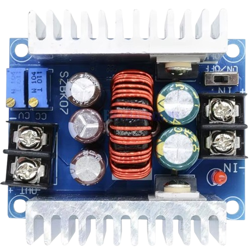
The Step Down Buck Converter (Manufacturer Part ID: 20A 300W) is a type of DC-DC converter designed to step down voltage from its input to its output while maintaining high efficiency. This component is essential in power supply circuits where there is a need to reduce voltage levels. It is widely used in various applications, including battery-powered devices, power management systems, and embedded systems.

Explore Projects Built with Step Down Buck converter

Use Cirkit Designer to design, explore, and prototype these projects online. Some projects support real-time simulation. Click "Open Project" to start designing instantly!
Battery-Powered UPS with Step-Down Buck Converter and BMS
Image of Mini ups: A project utilizing Step Down Buck converter in a practical application
This circuit is a power management system that steps down a 240V AC input to a lower DC voltage using a buck converter, which then powers a 40W UPS. The UPS is controlled by a rocker switch and is backed up by a battery management system (BMS) connected to three 3.7V batteries in series, ensuring continuous power supply.
Cirkit Designer LogoOpen Project in Cirkit Designer
USB Power Supply with Overcurrent Protection
Image of USB Charging port: A project utilizing Step Down Buck converter in a practical application
This circuit is designed to step down voltage from a 12V battery to a lower voltage suitable for USB devices. It includes a buck converter connected to the battery through a fuse and fuse holder for overcurrent protection. The output of the buck converter is connected to a USB female port, providing a regulated power supply for USB-powered devices.
Cirkit Designer LogoOpen Project in Cirkit Designer
Battery-Powered DC Generator with XL4015 Buck Converter
Image of conveyor: A project utilizing Step Down Buck converter in a practical application
This circuit consists of a 12V battery connected to a rocker switch, which controls the input to an XL4015 DC Buck Step-down converter. The converter steps down the voltage to power a DC generator, with the generator's output connected back to the converter to form a feedback loop.
Cirkit Designer LogoOpen Project in Cirkit Designer
Dual Motor Control Circuit with Directional Switching and Voltage Regulation
Image of Pencuci Kipas: A project utilizing Step Down Buck converter in a practical application
This circuit features a 12V battery connected through a rocker switch to two buck converters, one of which steps down the voltage to power two DC mini metal gear motors, and the other is connected to a directional switch that controls a third DC mini metal gear motor. The XL4015 5A DC Buck Step-down converter's output is connected to two motors, allowing them to run at a reduced voltage, while the other buck converter's output is routed through a directional switch to control the direction of the third motor.
Cirkit Designer LogoOpen Project in Cirkit Designer

Explore Projects Built with Step Down Buck converter

Use Cirkit Designer to design, explore, and prototype these projects online. Some projects support real-time simulation. Click "Open Project" to start designing instantly!
Image of Mini ups: A project utilizing Step Down Buck converter in a practical application
Battery-Powered UPS with Step-Down Buck Converter and BMS
This circuit is a power management system that steps down a 240V AC input to a lower DC voltage using a buck converter, which then powers a 40W UPS. The UPS is controlled by a rocker switch and is backed up by a battery management system (BMS) connected to three 3.7V batteries in series, ensuring continuous power supply.
Cirkit Designer LogoOpen Project in Cirkit Designer
Image of USB Charging port: A project utilizing Step Down Buck converter in a practical application
USB Power Supply with Overcurrent Protection
This circuit is designed to step down voltage from a 12V battery to a lower voltage suitable for USB devices. It includes a buck converter connected to the battery through a fuse and fuse holder for overcurrent protection. The output of the buck converter is connected to a USB female port, providing a regulated power supply for USB-powered devices.
Cirkit Designer LogoOpen Project in Cirkit Designer
Image of conveyor: A project utilizing Step Down Buck converter in a practical application
Battery-Powered DC Generator with XL4015 Buck Converter
This circuit consists of a 12V battery connected to a rocker switch, which controls the input to an XL4015 DC Buck Step-down converter. The converter steps down the voltage to power a DC generator, with the generator's output connected back to the converter to form a feedback loop.
Cirkit Designer LogoOpen Project in Cirkit Designer
Image of Pencuci Kipas: A project utilizing Step Down Buck converter in a practical application
Dual Motor Control Circuit with Directional Switching and Voltage Regulation
This circuit features a 12V battery connected through a rocker switch to two buck converters, one of which steps down the voltage to power two DC mini metal gear motors, and the other is connected to a directional switch that controls a third DC mini metal gear motor. The XL4015 5A DC Buck Step-down converter's output is connected to two motors, allowing them to run at a reduced voltage, while the other buck converter's output is routed through a directional switch to control the direction of the third motor.
Cirkit Designer LogoOpen Project in Cirkit Designer

Technical Specifications

Key Technical Details

Parameter Value
Input Voltage 6V - 40V
Output Voltage 1.2V - 36V
Output Current Up to 20A
Power Rating 300W
Efficiency Up to 95%
Switching Frequency 150kHz
Operating Temperature -40°C to +85°C

Pin Configuration and Descriptions

Pin Number Pin Name Description
1 VIN Input Voltage (6V - 40V)
2 GND Ground
3 VOUT Output Voltage (1.2V - 36V)
4 ADJ Output Voltage Adjustment

Usage Instructions

How to Use the Component in a Circuit

  1. Connect the Input Voltage (VIN): Connect the positive terminal of your power source to the VIN pin and the negative terminal to the GND pin.
  2. Connect the Output Load (VOUT): Connect the load that requires the stepped-down voltage to the VOUT pin and the GND pin.
  3. Adjust the Output Voltage (ADJ): Use a potentiometer or a fixed resistor to adjust the output voltage to the desired level. The ADJ pin allows fine-tuning of the output voltage.

Important Considerations and Best Practices

  • Heat Dissipation: Ensure proper heat dissipation by using a heatsink or placing the converter in a well-ventilated area, especially when operating at high currents.
  • Input Voltage Range: Always ensure that the input voltage is within the specified range (6V - 40V) to avoid damaging the converter.
  • Output Voltage Adjustment: When adjusting the output voltage, start with a low setting and gradually increase to the desired level to prevent overshooting.
  • Load Requirements: Ensure that the load connected to the output does not exceed the maximum current rating (20A) to avoid overloading the converter.

Example Circuit with Arduino UNO

Here is an example of how to use the Step Down Buck Converter with an Arduino UNO to power a 5V sensor:

Circuit Diagram

+---------+       +-------------------+
| Arduino |       | Step Down Buck    |
|   UNO   |       | Converter         |
|         |       |                   |
|   VIN   |-------| VIN               |
|   GND   |-------| GND               |
|   5V    |-------| VOUT              |
|         |       |                   |
+---------+       +-------------------+

Arduino Code

// Example code to read a sensor powered by the Step Down Buck Converter

const int sensorPin = A0; // Analog pin connected to the sensor
int sensorValue = 0;      // Variable to store the sensor value

void setup() {
  Serial.begin(9600); // Initialize serial communication at 9600 baud
}

void loop() {
  sensorValue = analogRead(sensorPin); // Read the sensor value
  Serial.print("Sensor Value: ");
  Serial.println(sensorValue); // Print the sensor value to the serial monitor
  delay(1000); // Wait for 1 second before reading again
}

Troubleshooting and FAQs

Common Issues Users Might Face

  1. No Output Voltage:

    • Solution: Check the input voltage to ensure it is within the specified range. Verify all connections are secure and correct.
  2. Overheating:

    • Solution: Ensure proper heat dissipation by using a heatsink or placing the converter in a well-ventilated area. Reduce the load if necessary.
  3. Output Voltage Not Adjustable:

    • Solution: Verify the connection to the ADJ pin and ensure the potentiometer or resistor used for adjustment is functioning correctly.

FAQs

  1. Can I use this converter with a battery?

    • Yes, the Step Down Buck Converter can be used with a battery as long as the input voltage is within the specified range (6V - 40V).
  2. What is the maximum output current?

    • The maximum output current is 20A. Ensure that the load connected does not exceed this rating.
  3. How do I adjust the output voltage?

    • Use a potentiometer or a fixed resistor connected to the ADJ pin to adjust the output voltage. Start with a low setting and gradually increase to the desired level.

By following this documentation, users can effectively utilize the Step Down Buck Converter in their projects, ensuring efficient and reliable voltage regulation.