How to Use Buck Converter 3A: Examples, Pinouts, and Specs
Introduction
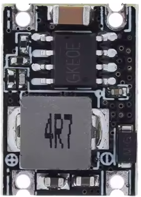
A buck converter, also known as a step-down DC-DC converter, is an electronic component designed to reduce a higher input voltage to a lower output voltage while maintaining high efficiency. The Buck Converter 3A, manufactured in China, is capable of delivering a maximum output current of 3A, making it ideal for powering devices that require lower voltage and moderate current. Its compact size and high efficiency make it a popular choice for battery-powered systems, embedded devices, and other low-voltage applications.
Explore Projects Built with Buck Converter 3A


Explore Projects Built with Buck Converter 3A
Common Applications and Use Cases
- Powering microcontrollers, sensors, and modules in embedded systems
- Voltage regulation for battery-powered devices
- Supplying power to LED strips and low-voltage motors
- Step-down voltage conversion in robotics and IoT projects
- Efficient power delivery in portable electronics
Technical Specifications
The Buck Converter 3A is designed to provide reliable and efficient voltage regulation. Below are its key technical specifications:
| Parameter | Value |
|---|---|
| Input Voltage Range | 4.5V to 28V |
| Output Voltage Range | 0.8V to 20V (adjustable) |
| Maximum Output Current | 3A |
| Efficiency | Up to 92% (depending on load) |
| Switching Frequency | 150 kHz |
| Operating Temperature | -40°C to +85°C |
| Dimensions | Typically 22mm x 17mm x 4mm |
Pin Configuration and Descriptions
The Buck Converter 3A typically has the following pin configuration:
| Pin Name | Description |
|---|---|
| VIN | Input voltage pin. Connect to the positive terminal of the input power source. |
| GND | Ground pin. Connect to the negative terminal of the input power source. |
| VOUT | Output voltage pin. Provides the regulated output voltage. |
| ADJ (optional) | Adjustment pin. Used to set the output voltage (if adjustable). |
Usage Instructions
How to Use the Buck Converter 3A in a Circuit
- Connect the Input Voltage:
- Connect the VIN pin to the positive terminal of your power source (e.g., a battery or DC power supply).
- Connect the GND pin to the negative terminal of your power source.
- Set the Output Voltage (if adjustable):
- Use the onboard potentiometer (if available) to adjust the output voltage. Turn the potentiometer clockwise or counterclockwise while monitoring the output voltage with a multimeter.
- Connect the Load:
- Connect the VOUT pin to the positive terminal of your load (e.g., a microcontroller or LED strip).
- Connect the GND pin to the negative terminal of your load.
- Power On:
- Turn on the input power source and verify the output voltage using a multimeter before connecting sensitive devices.
Important Considerations and Best Practices
- Ensure the input voltage is within the specified range (4.5V to 28V) to avoid damaging the converter.
- Do not exceed the maximum output current of 3A to prevent overheating or failure.
- Use appropriate heat dissipation methods (e.g., a heatsink) if operating near the maximum current limit.
- Place decoupling capacitors near the input and output pins to reduce noise and improve stability.
- If using the converter with an Arduino UNO or similar microcontroller, ensure the output voltage matches the microcontroller's operating voltage (e.g., 5V or 3.3V).
Example: Using the Buck Converter 3A with an Arduino UNO
Below is an example of how to connect the Buck Converter 3A to an Arduino UNO:
- Set the output voltage of the buck converter to 5V using the onboard potentiometer.
- Connect the VIN and GND pins of the buck converter to a 12V DC power source.
- Connect the VOUT pin of the buck converter to the 5V pin of the Arduino UNO.
- Connect the GND pin of the buck converter to the GND pin of the Arduino UNO.
Here is a simple Arduino code example to blink an LED using the regulated 5V output:
// This code blinks an LED connected to pin 13 of the Arduino UNO.
// Ensure the buck converter is providing a stable 5V to the Arduino.

void setup() {
  pinMode(13, OUTPUT); // Set pin 13 as an output pin
}

void loop() {
  digitalWrite(13, HIGH); // Turn the LED on
  delay(1000);            // Wait for 1 second
  digitalWrite(13, LOW);  // Turn the LED off
  delay(1000);            // Wait for 1 second
}
Troubleshooting and FAQs
Common Issues and Solutions
No Output Voltage:
- Verify that the input voltage is within the specified range (4.5V to 28V).
- Check all connections to ensure they are secure and correctly wired.
- Inspect the onboard potentiometer (if adjustable) to ensure it is not set to 0V.
Overheating:
- Ensure the load does not exceed the maximum output current of 3A.
- Use a heatsink or active cooling if operating near the maximum current limit.
Output Voltage Fluctuations:
- Add decoupling capacitors (e.g., 10µF and 0.1µF) near the input and output pins.
- Check for loose connections or poor solder joints.
Load Not Powering On:
- Verify that the output voltage matches the load's required operating voltage.
- Check the load's current requirements to ensure they do not exceed 3A.
FAQs
Q: Can I use the Buck Converter 3A with a 24V input to power a 5V device?
A: Yes, the converter can step down 24V to 5V as long as the input voltage is within the 4.5V to 28V range and the load current does not exceed 3A.
Q: Is the output voltage stable enough for sensitive electronics?
A: Yes, the Buck Converter 3A provides a stable output voltage with high efficiency. Adding decoupling capacitors can further improve stability.
Q: Can I use this converter to charge a battery?
A: While it is possible, ensure the output voltage and current are suitable for the specific battery type. A dedicated battery charging circuit is recommended for optimal safety and performance.
Q: What happens if I exceed the 3A current limit?
A: Exceeding the current limit may cause the converter to overheat, shut down, or fail. Always ensure the load current is within the specified limit.