
How to Use ESP32- 32U DEV KIT: Examples, Pinouts, and Specs
 Design with ESP32- 32U DEV KIT in Cirkit Designer
Introduction
The ESP32-32U DEV KIT is a versatile microcontroller development board based on the ESP32 chip. It features built-in Wi-Fi and Bluetooth capabilities, making it an excellent choice for Internet of Things (IoT) applications, wireless communication projects, and rapid prototyping. With its dual-core processor, low power consumption, and extensive GPIO pins, the ESP32-32U DEV KIT is suitable for a wide range of applications, from smart home devices to industrial automation.
Explore Projects Built with ESP32- 32U DEV KIT
 Open Project in Cirkit Designer
 Open Project in Cirkit Designer
 Open Project in Cirkit Designer
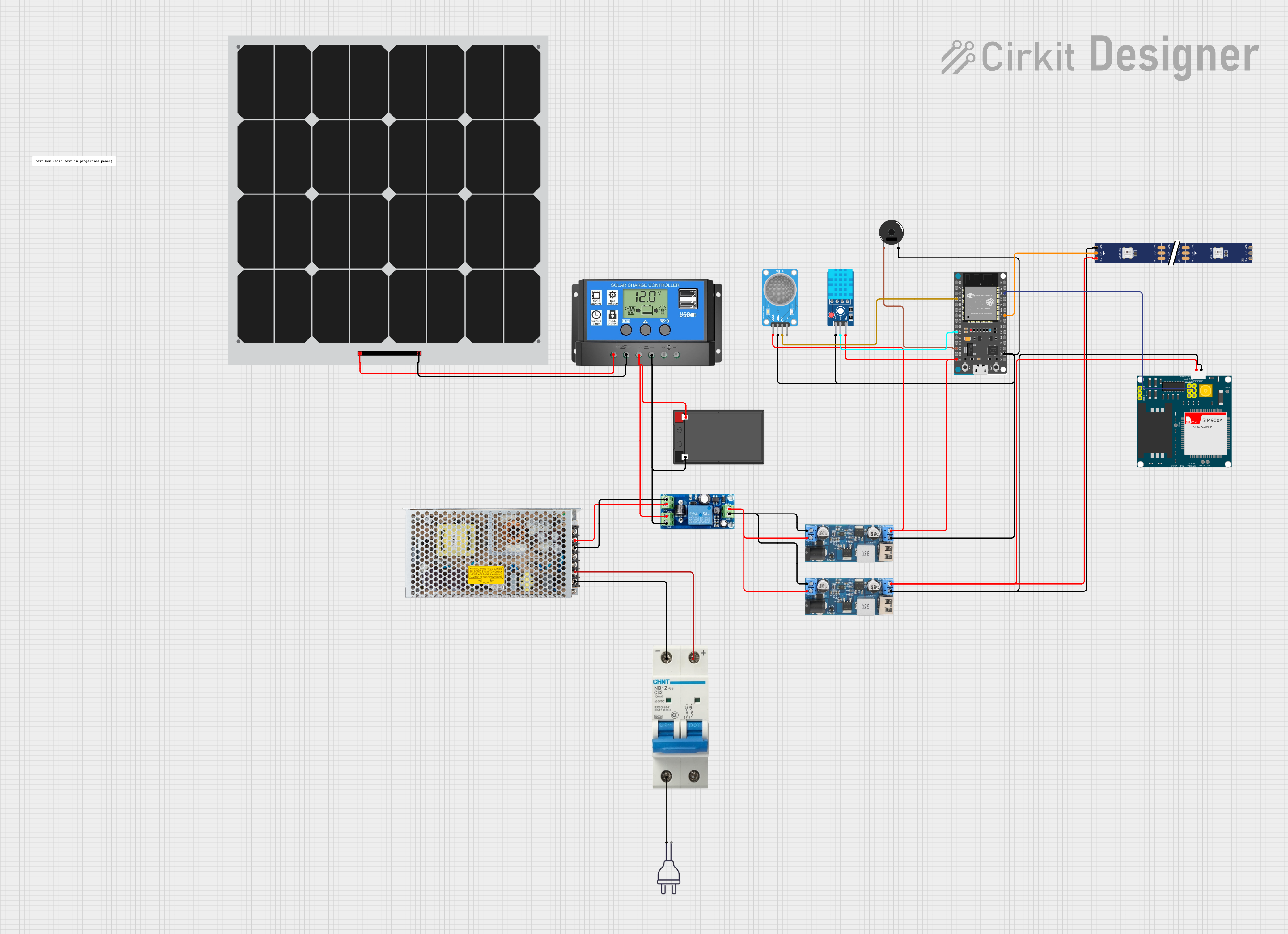 Open Project in Cirkit Designer
Explore Projects Built with ESP32- 32U DEV KIT
Open Project in Cirkit DesignerOpen Project in Cirkit DesignerOpen Project in Cirkit DesignerOpen Project in Cirkit DesignerCommon Applications and Use Cases
- IoT devices and smart home automation
- Wireless sensor networks
- Bluetooth-enabled devices
- Data logging and remote monitoring
- Robotics and automation systems
- Prototyping for embedded systems
Technical Specifications
The ESP32-32U DEV KIT is designed to provide robust performance and flexibility. Below are its key technical specifications:
| Specification | Details |
|---|---|
| Microcontroller | ESP32 (dual-core Xtensa LX6 processor) |
| Clock Speed | Up to 240 MHz |
| Flash Memory | 4 MB (varies by model) |
| SRAM | 520 KB |
| Wireless Connectivity | Wi-Fi 802.11 b/g/n, Bluetooth v4.2 + BLE |
| Operating Voltage | 3.3V |
| Input Voltage (VIN) | 5V (via USB or external power supply) |
| GPIO Pins | 30+ (multipurpose, including ADC, DAC, PWM, I2C, SPI, UART) |
| ADC Channels | 18 (12-bit resolution) |
| DAC Channels | 2 |
| Communication Interfaces | UART, SPI, I2C, I2S, CAN, PWM |
| Power Consumption | Ultra-low power consumption in deep sleep mode (as low as 10 µA) |
| Dimensions | 54 mm x 27 mm |
Pin Configuration and Descriptions
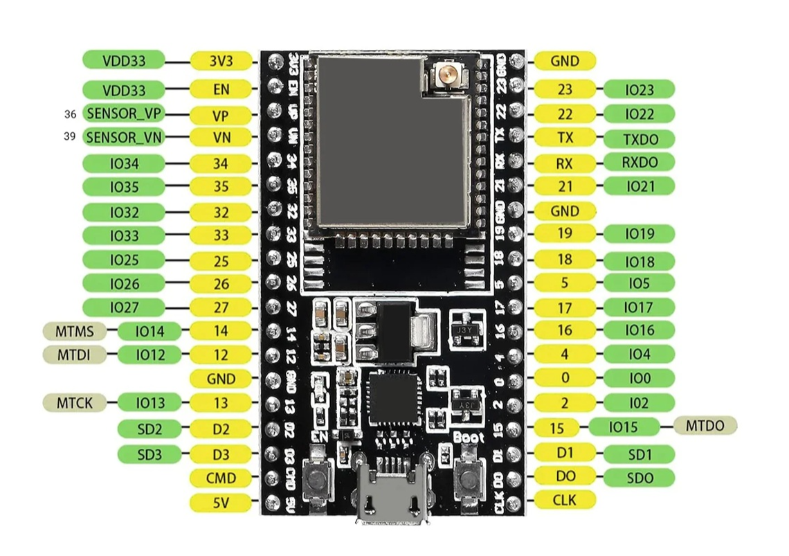
The ESP32-32U DEV KIT has a variety of pins for different functionalities. Below is a summary of the pin configuration:
| Pin | Function | Description |
|---|---|---|
| VIN | Power Input | Connect to 5V power supply (via USB or external source). |
| GND | Ground | Common ground for the circuit. |
| 3V3 | Power Output | Provides 3.3V output for external components. |
| EN | Enable | Used to enable or reset the ESP32 chip. |
| GPIO0 | Boot Mode / General Purpose I/O | Used for boot mode selection or as a general-purpose I/O pin. |
| GPIO2 | General Purpose I/O | Can be used for PWM, ADC, or other functions. |
| GPIO16 | General Purpose I/O | Supports UART, I2C, and other communication protocols. |
| TXD0 | UART Transmit | UART0 transmit pin for serial communication. |
| RXD0 | UART Receive | UART0 receive pin for serial communication. |
| ADC1 | Analog Input | 12-bit ADC input for reading analog signals. |
| DAC1 | Digital-to-Analog Converter | Outputs analog signals (e.g., for audio or control applications). |
| IO34-39 | Input Only | These pins are input-only and cannot be used for output. |
Note: Some GPIO pins have specific functions or limitations. Refer to the ESP32 datasheet for detailed pin capabilities.
Usage Instructions
How to Use the ESP32-32U DEV KIT in a Circuit
Powering the Board:
- Connect the board to a computer or USB power supply using a micro-USB cable.
- Alternatively, supply 5V to the VIN pin and connect GND to the ground of your power source.
Programming the Board:
- Install the Arduino IDE or ESP-IDF (Espressif IoT Development Framework).
- Add the ESP32 board support package to the Arduino IDE via the Board Manager.
- Select "ESP32 Dev Module" as the board type in the IDE.
- Connect the board to your computer and upload your code.
Connecting Peripherals:
- Use the GPIO pins to connect sensors, actuators, or other peripherals.
- Ensure that the voltage levels of connected devices are compatible with the ESP32 (3.3V logic).
Wi-Fi and Bluetooth Setup:
- Use the built-in libraries (e.g.,
WiFi.handBluetoothSerial.h) to configure wireless communication.
- Use the built-in libraries (e.g.,
Important Considerations and Best Practices
- Voltage Levels: The ESP32 operates at 3.3V logic. Avoid connecting 5V signals directly to GPIO pins.
- Deep Sleep Mode: Use deep sleep mode to conserve power in battery-powered applications.
- Boot Mode: Ensure GPIO0 is pulled low during boot to enter programming mode.
- Heat Management: The ESP32 may heat up during operation. Ensure proper ventilation if used in enclosed spaces.
Example Code for Arduino IDE
The following example demonstrates how to connect the ESP32 to a Wi-Fi network and print the IP address:
#include <WiFi.h> // Include the WiFi library

const char* ssid = "Your_SSID";       // Replace with your Wi-Fi network name
const char* password = "Your_Password"; // Replace with your Wi-Fi password

void setup() {
  Serial.begin(115200); // Initialize serial communication at 115200 baud
  delay(1000);          // Wait for the serial monitor to initialize

  Serial.println("Connecting to Wi-Fi...");
  WiFi.begin(ssid, password); // Start Wi-Fi connection

  while (WiFi.status() != WL_CONNECTED) {
    delay(500); // Wait for connection
    Serial.print(".");
  }

  Serial.println("\nWi-Fi connected!");
  Serial.print("IP Address: ");
  Serial.println(WiFi.localIP()); // Print the assigned IP address
}

void loop() {
  // Add your main code here
}
Tip: Replace
Your_SSIDandYour_Passwordwith your Wi-Fi credentials.
Troubleshooting and FAQs
Common Issues and Solutions
ESP32 Not Detected by Computer:
- Ensure the USB cable is functional and supports data transfer.
- Install the correct USB-to-serial driver (e.g., CP2102 or CH340).
Upload Fails with "Failed to Connect" Error:
- Press and hold the "BOOT" button on the board while uploading the code.
- Check that the correct COM port is selected in the Arduino IDE.
Wi-Fi Connection Issues:
- Verify the SSID and password are correct.
- Ensure the Wi-Fi network is within range and not using unsupported security protocols.
GPIO Pin Not Working:
- Check if the pin is reserved for specific functions (e.g., boot mode).
- Ensure the pin is not overloaded or shorted.
FAQs
Q: Can I power the ESP32-32U DEV KIT with a battery?
A: Yes, you can use a 3.7V LiPo battery connected to the 3V3 pin or a 5V source connected to the VIN pin.
Q: How do I reset the ESP32?
A: Press the "EN" button on the board to reset the ESP32.
Q: Can I use the ESP32 with 5V sensors?
A: Use a level shifter to safely interface 5V sensors with the 3.3V GPIO pins of the ESP32.
Q: What is the maximum range of the ESP32's Wi-Fi?
A: The range depends on environmental factors but typically extends up to 100 meters in open spaces.
By following this documentation, you can effectively utilize the ESP32-32U DEV KIT for your projects and troubleshoot common issues with ease.