How to Use CONTATOR: Examples, Pinouts, and Specs
Introduction
A contactor is an electrically controlled switch designed for switching power circuits. It operates similarly to a relay but is specifically engineered to handle higher currents, making it ideal for industrial and commercial applications. Contactors are widely used in motor control systems, lighting circuits, and heating equipment, where they enable the safe and efficient control of high-power loads.
Explore Projects Built with CONTATOR


Explore Projects Built with CONTATOR
Common Applications and Use Cases
- Motor Control: Starting, stopping, and reversing motors in industrial machinery.
- Lighting Systems: Controlling large lighting loads in commercial buildings.
- Heating Equipment: Switching high-power heating elements in HVAC systems.
- Power Distribution: Managing power circuits in industrial automation systems.
Technical Specifications
Below are the general technical specifications for a typical contactor. Note that specific values may vary depending on the model and manufacturer.
Key Technical Details
- Operating Voltage: 24V DC, 48V DC, 110V AC, 230V AC, or 400V AC (varies by model)
- Coil Power Consumption: 3-10W (depending on size and type)
- Contact Ratings:
- Current: 9A to 800A (depending on the application)
- Voltage: Up to 1000V AC
- Number of Poles: 1P, 2P, 3P, or 4P
- Mechanical Life: Up to 10 million operations
- Electrical Life: Up to 1 million operations (depending on load)
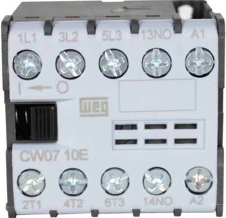
Pin Configuration and Descriptions
The pin configuration of a contactor typically includes terminals for the coil and the main power contacts. Below is a general description:
| Pin/Terminal | Description |
|---|---|
| A1 | Coil positive terminal (used to energize the contactor) |
| A2 | Coil negative terminal (used to energize the contactor) |
| L1, L2, L3 | Input terminals for the main power circuit (for 3-phase systems) |
| T1, T2, T3 | Output terminals for the main power circuit (for 3-phase systems) |
| NO (Normally Open) | Auxiliary contact terminal (closes when the contactor is energized) |
| NC (Normally Closed) | Auxiliary contact terminal (opens when the contactor is energized) |
Usage Instructions
How to Use the Contactor in a Circuit
- Determine the Coil Voltage: Verify the operating voltage of the contactor's coil and ensure it matches the control circuit's voltage.
- Connect the Coil Terminals:
- Connect the positive control signal to terminal A1.
- Connect the negative control signal (or ground) to terminal A2.
- Connect the Power Circuit:
- For a 3-phase system, connect the input power lines to L1, L2, and L3.
- Connect the load (e.g., motor) to T1, T2, and T3.
- Use Auxiliary Contacts (if needed):
- Connect auxiliary devices (e.g., indicator lights or interlocks) to the NO or NC terminals.
- Test the Circuit: Energize the coil to verify that the contactor operates correctly and switches the power circuit.
Important Considerations and Best Practices
- Overload Protection: Always use an appropriate overload relay in conjunction with the contactor to protect the load.
- Voltage Ratings: Ensure the contactor's voltage and current ratings match the application requirements.
- Mounting: Securely mount the contactor on a DIN rail or panel to prevent vibration or movement.
- Noise Suppression: Use a snubber circuit or RC suppressor across the coil terminals to reduce electrical noise and prolong the contactor's life.
- Maintenance: Periodically inspect the contactor for wear, dirt, or damage to ensure reliable operation.
Example: Contactor Control with Arduino UNO
Below is an example of how to control a 24V DC contactor using an Arduino UNO and a relay module.
// Example: Controlling a 24V DC contactor with Arduino UNO
// This code energizes the contactor for 5 seconds, then de-energizes it.

const int relayPin = 7; // Pin connected to the relay module

void setup() {
  pinMode(relayPin, OUTPUT); // Set the relay pin as an output
  digitalWrite(relayPin, LOW); // Ensure the relay is off initially
}

void loop() {
  digitalWrite(relayPin, HIGH); // Turn on the relay (energize the contactor)
  delay(5000); // Keep the contactor energized for 5 seconds
  digitalWrite(relayPin, LOW); // Turn off the relay (de-energize the contactor)
  delay(5000); // Wait for 5 seconds before repeating
}
Note: Ensure the relay module is rated to handle the contactor's coil current. Use an external power supply for the contactor if its coil voltage exceeds the Arduino's output voltage.
Troubleshooting and FAQs
Common Issues and Solutions
Contactor Does Not Energize:
- Cause: Incorrect coil voltage or loose connections.
- Solution: Verify the coil voltage and ensure all connections are secure.
Excessive Noise or Chattering:
- Cause: Insufficient control voltage or electrical noise.
- Solution: Check the control voltage and use a snubber circuit or RC suppressor.
Contacts Overheat:
- Cause: Overloaded contacts or poor ventilation.
- Solution: Ensure the contactor's current rating matches the load and improve ventilation.
Short Mechanical Life:
- Cause: Frequent switching or poor maintenance.
- Solution: Use a contactor rated for high switching cycles and perform regular maintenance.
FAQs
Q: Can I use a contactor for DC loads?
- A: Yes, but ensure the contactor is specifically rated for DC applications, as DC arcs are harder to extinguish than AC arcs.
Q: What is the difference between a contactor and a relay?
- A: Contactors are designed for higher current loads and often include auxiliary contacts, while relays are typically used for lower current applications.
Q: How do I select the right contactor for my application?
- A: Consider the load's voltage, current, and type (AC or DC), as well as the required number of poles and auxiliary contacts.
Q: Can I manually operate a contactor?
- A: Some contactors include a manual override feature, but this is not common in all models. Always check the manufacturer's specifications.