
How to Use Attenuator: Examples, Pinouts, and Specs
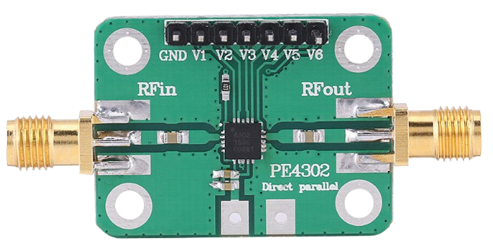
 Design with Attenuator in Cirkit Designer
Introduction
An attenuator is an electronic component designed to reduce the power of a signal without distorting its waveform. It is commonly used in audio and radio frequency (RF) applications to control signal levels, ensuring that signals are within the desired range for processing or transmission. Attenuators are essential in preventing signal overload, protecting sensitive equipment, and achieving precise signal control in various systems.
Explore Projects Built with Attenuator
 Open Project in Cirkit Designer
 Open Project in Cirkit Designer
 Open Project in Cirkit Designer
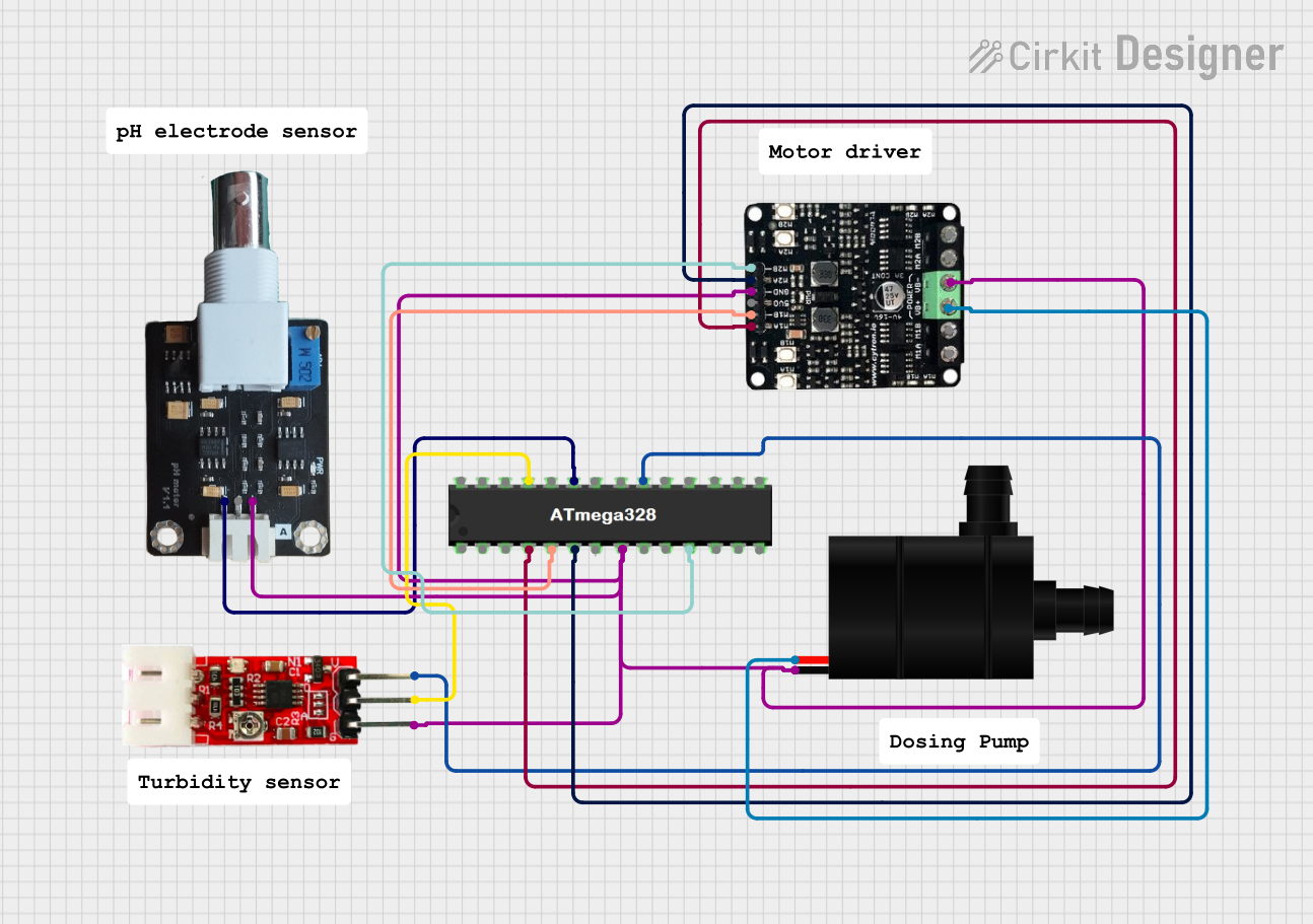 Open Project in Cirkit Designer
Explore Projects Built with Attenuator
Open Project in Cirkit DesignerOpen Project in Cirkit DesignerOpen Project in Cirkit DesignerOpen Project in Cirkit DesignerCommon Applications and Use Cases
- Audio Systems: To adjust volume levels or match signal levels between devices.
- RF Communication: To reduce signal strength for testing or to prevent overloading receivers.
- Measurement Equipment: To protect sensitive instruments from high-power signals.
- Impedance Matching: To ensure proper signal transfer between devices with different impedance levels.
Technical Specifications
Attenuators are available in various configurations, such as fixed, variable, and step attenuators. Below are the general technical specifications for a typical attenuator:
Key Technical Details
- Frequency Range: DC to GHz (varies by model)
- Attenuation Levels: 1 dB to 100 dB (fixed or adjustable)
- Power Handling: Up to 100 W (depending on the design)
- Impedance: 50 Ω or 75 Ω (common for RF applications)
- VSWR (Voltage Standing Wave Ratio): Typically ≤ 1.2:1
- Connector Types: SMA, BNC, N-type, or others (depending on application)
Pin Configuration and Descriptions
For a basic attenuator module with input and output pins, the configuration is as follows:
| Pin | Name | Description |
|---|---|---|
| 1 | Input | Signal input pin where the high-power signal is applied. |
| 2 | Output | Signal output pin where the attenuated signal is delivered. |
| 3 | Ground (GND) | Ground connection for the attenuator circuit. |
For more complex attenuators with control pins (e.g., digital step attenuators), the configuration may include additional pins:
| Pin | Name | Description |
|---|---|---|
| 1 | Input | Signal input pin where the high-power signal is applied. |
| 2 | Output | Signal output pin where the attenuated signal is delivered. |
| 3 | Ground (GND) | Ground connection for the attenuator circuit. |
| 4 | Control Pin 1 | Digital control pin to set the attenuation level (e.g., LSB for step attenuator). |
| 5 | Control Pin 2 | Additional control pin for setting attenuation (e.g., MSB for step attenuator). |
Usage Instructions
How to Use the Component in a Circuit
- Determine the Required Attenuation: Calculate the desired attenuation level based on your application. For example, in RF systems, ensure the signal strength is within the receiver's dynamic range.
- Connect the Input and Output:
- Connect the signal source to the Input pin of the attenuator.
- Connect the Output pin to the next stage of your circuit (e.g., amplifier, receiver).
- Ground the Circuit: Ensure the Ground (GND) pin is properly connected to the system ground to avoid noise or interference.
- Adjust Attenuation (if applicable): For variable or step attenuators, use the control pins or knobs to set the desired attenuation level.
Important Considerations and Best Practices
- Impedance Matching: Ensure the attenuator's impedance matches the source and load impedance (e.g., 50 Ω for RF systems).
- Power Handling: Verify that the attenuator can handle the maximum power of the input signal to avoid damage.
- Frequency Range: Use an attenuator that supports the frequency range of your application to prevent signal distortion.
- Minimize Signal Loss: Use high-quality connectors and cables to reduce additional signal loss.
Example: Using a Digital Step Attenuator with Arduino UNO
Below is an example of controlling a digital step attenuator using an Arduino UNO:
// Example code to control a digital step attenuator with Arduino UNO
// This assumes a 2-bit control attenuator with Control Pin 1 (LSB) and Control Pin 2 (MSB)

const int controlPin1 = 8; // Connect to Control Pin 1 of the attenuator
const int controlPin2 = 9; // Connect to Control Pin 2 of the attenuator

void setup() {
  pinMode(controlPin1, OUTPUT); // Set Control Pin 1 as output
  pinMode(controlPin2, OUTPUT); // Set Control Pin 2 as output
}

void loop() {
  // Example: Set attenuation to 0 dB (binary 00)
  digitalWrite(controlPin1, LOW);
  digitalWrite(controlPin2, LOW);
  delay(1000); // Wait for 1 second

  // Example: Set attenuation to 10 dB (binary 01)
  digitalWrite(controlPin1, HIGH);
  digitalWrite(controlPin2, LOW);
  delay(1000); // Wait for 1 second

  // Example: Set attenuation to 20 dB (binary 10)
  digitalWrite(controlPin1, LOW);
  digitalWrite(controlPin2, HIGH);
  delay(1000); // Wait for 1 second

  // Example: Set attenuation to 30 dB (binary 11)
  digitalWrite(controlPin1, HIGH);
  digitalWrite(controlPin2, HIGH);
  delay(1000); // Wait for 1 second
}
Troubleshooting and FAQs
Common Issues Users Might Face
Signal Distortion:
- Cause: Using an attenuator outside its specified frequency range.
- Solution: Verify the frequency range of the attenuator and ensure compatibility with your application.
Excessive Signal Loss:
- Cause: Poor-quality connectors or cables.
- Solution: Use high-quality, low-loss connectors and cables.
Overheating:
- Cause: Input signal power exceeds the attenuator's power rating.
- Solution: Check the power rating of the attenuator and ensure the input signal is within limits.
Incorrect Attenuation Level:
- Cause: Misconfigured control pins (for digital attenuators).
- Solution: Double-check the control pin connections and logic levels.
Solutions and Tips for Troubleshooting
- Use a multimeter or oscilloscope to verify signal levels at the input and output of the attenuator.
- Ensure all connections are secure and free from corrosion or damage.
- For digital attenuators, test the control signals with an LED or logic analyzer to confirm proper operation.
By following this documentation, users can effectively integrate and troubleshoot attenuators in their electronic systems.