How to Use Lamp Red: Examples, Pinouts, and Specs
Introduction
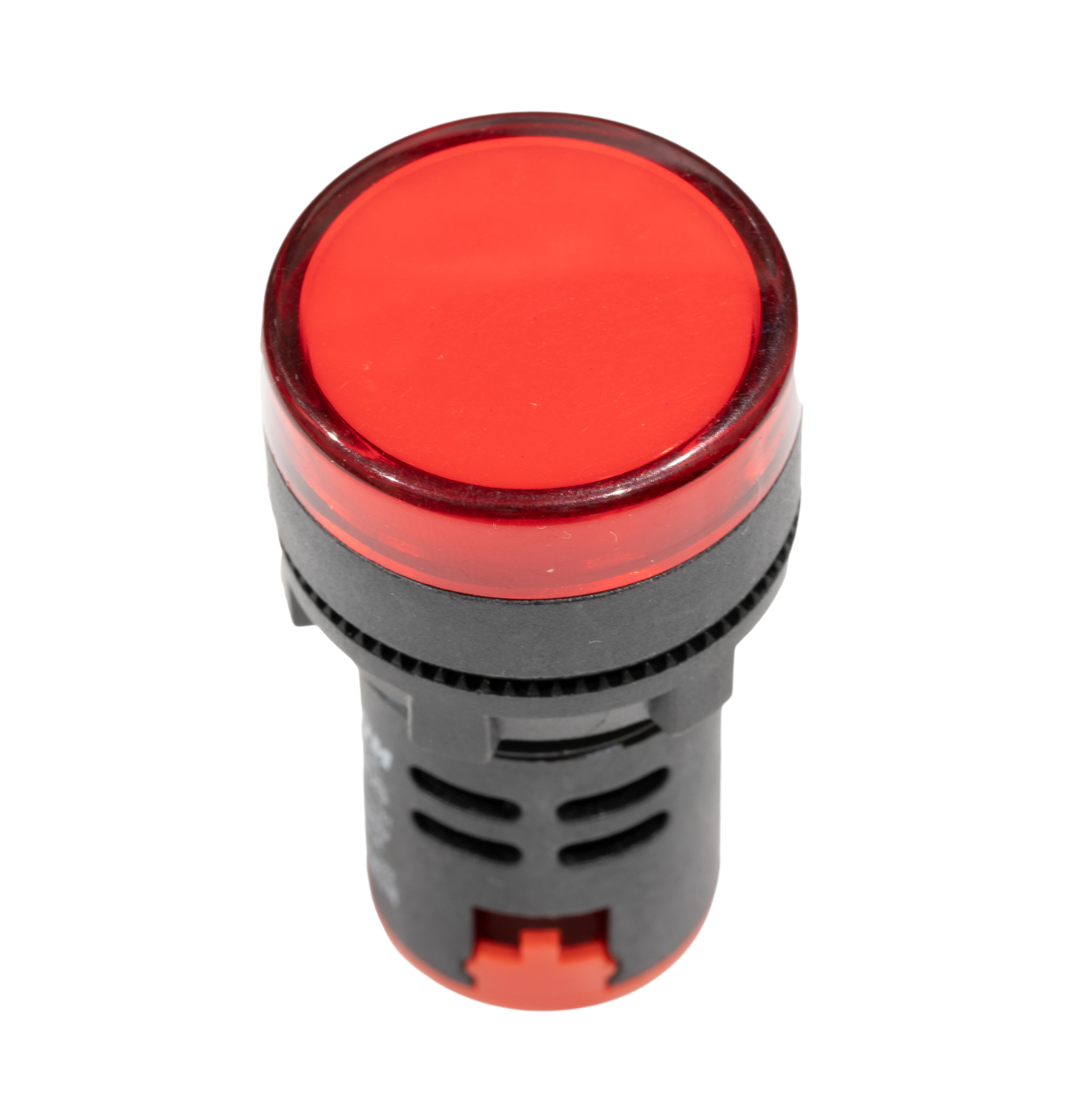
A red lamp is an electronic component designed to emit red light when an electric current is applied. It is commonly used as an indicator light in various electronic devices, control panels, and DIY projects. The red color is often chosen for its high visibility and is typically used to signal warnings, errors, or to indicate the status of a device.
Explore Projects Built with Lamp Red
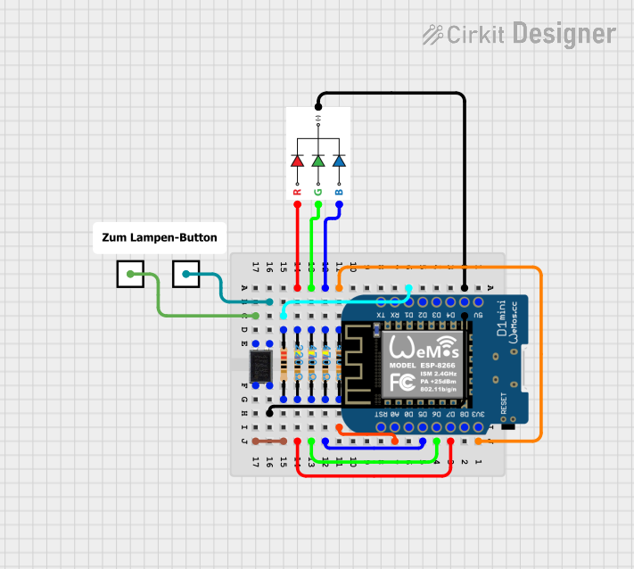
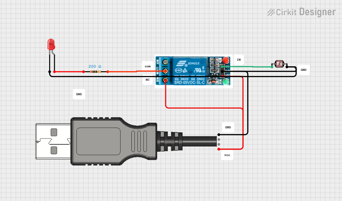
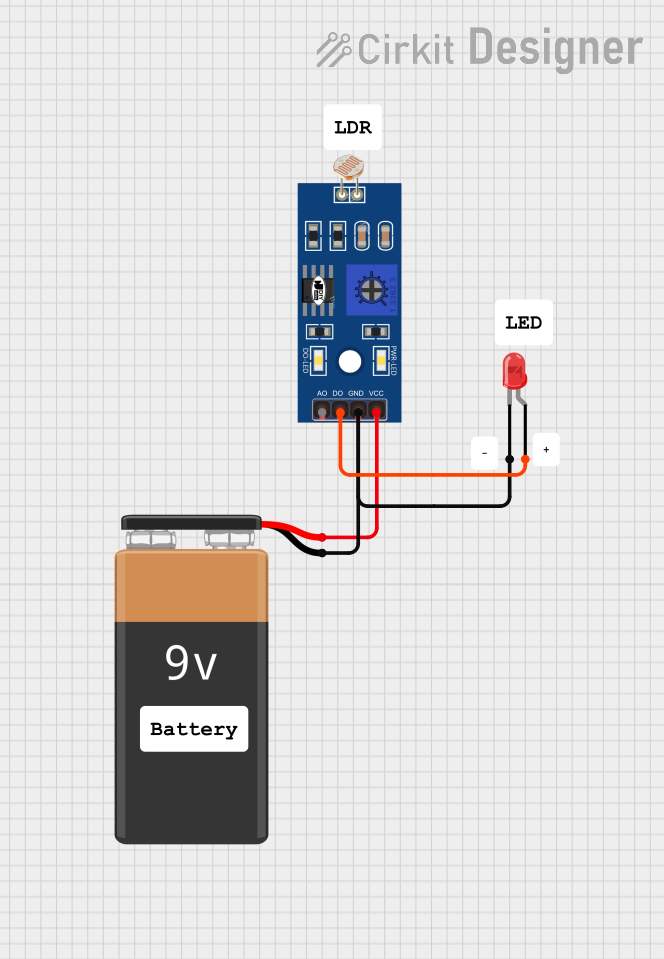

Explore Projects Built with Lamp Red
Common Applications and Use Cases
- Indicator light for power status
- Warning signal in safety equipment
- Display panels in electronic devices
- Decorative lighting in DIY projects
- Educational projects involving circuit design
Technical Specifications
Key Technical Details
- Nominal Voltage: 2V to 2.2V
- Forward Current: 20mA (typical operating current)
- Luminous Intensity: Depending on the specific model, can vary from 20 mcd to 200 mcd (millicandela)
- Wavelength: Approximately 625nm to 630nm (red light spectrum)
- Power Dissipation: 100mW
Pin Configuration and Descriptions
| Pin Number | Description |
|---|---|
| 1 | Anode (+) |
| 2 | Cathode (-) |
Usage Instructions
How to Use the Component in a Circuit
- Identify the anode and cathode pins of the red lamp. The longer lead is typically the anode (+), and the shorter lead is the cathode (-).
- Connect the anode to the positive side of the power supply, and the cathode to the negative side.
- Include a current-limiting resistor in series with the lamp to prevent excessive current flow. The value of the resistor can be calculated using Ohm's law:
R = (V_supply - V_lamp) / I_lamp, whereV_supplyis the supply voltage,V_lampis the lamp's voltage, andI_lampis the lamp's current.
Important Considerations and Best Practices
- Always use a current-limiting resistor to protect the lamp from overcurrent.
- Do not exceed the maximum ratings of voltage and current specified in the technical details.
- When soldering the lamp into a circuit, avoid excessive heat to prevent damage to the lamp.
Example Circuit with Arduino UNO
// Example code to control a red lamp using an Arduino UNO

const int lampPin = 13; // Connect the red lamp to digital pin 13

void setup() {
  pinMode(lampPin, OUTPUT); // Set the lamp pin as an output
}

void loop() {
  digitalWrite(lampPin, HIGH); // Turn on the red lamp
  delay(1000);                // Wait for 1 second
  digitalWrite(lampPin, LOW);  // Turn off the red lamp
  delay(1000);                // Wait for 1 second
}
Troubleshooting and FAQs
Common Issues Users Might Face
- Lamp not lighting up: Ensure the lamp is correctly oriented with the anode and cathode connected to the appropriate sides of the power supply. Check the current-limiting resistor and replace it if it's not the correct value.
- Lamp burned out: This could be due to applying too much voltage or current. Make sure the power supply does not exceed the lamp's maximum ratings.
- Dim light: If the lamp is emitting a dim light, the current may be too low. Verify that the current-limiting resistor is not too high in value.
Solutions and Tips for Troubleshooting
- Double-check the wiring and connections in your circuit.
- Use a multimeter to measure the voltage across the lamp and the current flowing through it.
- If the lamp fails to light up, replace it with a new one to rule out the possibility of a defective lamp.
FAQs
Q: Can I use a red lamp without a current-limiting resistor? A: No, using a red lamp without a current-limiting resistor can lead to the lamp burning out due to excessive current.
Q: How do I choose the right resistor value for my red lamp? A: Calculate the resistor value using Ohm's law, considering the supply voltage, the lamp's voltage, and the desired current.
Q: Is it possible to control the brightness of the red lamp? A: Yes, you can control the brightness by using a PWM (Pulse Width Modulation) signal to vary the average voltage applied to the lamp. This is easily done with microcontrollers like the Arduino UNO.
Q: Can I power the red lamp directly from an Arduino pin? A: Yes, as long as the current draw does not exceed the maximum current rating of the Arduino pin, which is typically 20mA. Always check the specifications of your microcontroller.