How to Use PIC: Examples, Pinouts, and Specs
Introduction
A PIC (Peripheral Interface Controller) is a family of microcontrollers developed by Microchip Technology. These microcontrollers are widely used in embedded systems due to their simplicity, low power consumption, and flexibility. PIC microcontrollers are available in a variety of configurations, making them suitable for a wide range of applications, from simple hobbyist projects to complex industrial systems.
Explore Projects Built with PIC

Explore Projects Built with PIC
Common Applications and Use Cases
- Home automation systems
- Motor control and robotics
- Sensor interfacing and data acquisition
- Consumer electronics
- Industrial automation
- IoT (Internet of Things) devices
Technical Specifications
Below are the general technical specifications for a typical PIC microcontroller. Note that specific models may vary in their features and capabilities.
Key Technical Details
- Operating Voltage: 2.0V to 5.5V (varies by model)
- Clock Speed: Up to 64 MHz (depending on the model and configuration)
- Flash Memory: 256 bytes to 1 MB
- RAM: 16 bytes to 128 KB
- EEPROM: 0 to 4 KB (non-volatile memory for data storage)
- I/O Pins: 6 to 100+ (depending on the package)
- Communication Protocols: UART, SPI, I2C, CAN, USB (varies by model)
- Timers: 8-bit and 16-bit timers
- ADC (Analog-to-Digital Converter): 8-bit to 12-bit resolution
- PWM (Pulse Width Modulation): Available on select pins
- Power Consumption: Ultra-low power modes available for energy-efficient applications
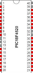
Pin Configuration and Descriptions
The pin configuration of a PIC microcontroller depends on the specific model. Below is an example of a typical 8-pin PIC microcontroller (e.g., PIC12F675):
| Pin Number | Pin Name | Description |
|---|---|---|
| 1 | VDD | Positive power supply (2.0V to 5.5V) |
| 2 | GP5 | General-purpose I/O pin |
| 3 | GP4 | General-purpose I/O pin |
| 4 | GP3/MCLR | General-purpose I/O or Master Clear pin |
| 5 | GP2 | General-purpose I/O pin |
| 6 | GP1 | General-purpose I/O pin |
| 7 | GP0 | General-purpose I/O pin |
| 8 | VSS | Ground (0V) |
For larger PIC microcontrollers, refer to the datasheet for the specific model to understand the pinout and functionality.
Usage Instructions
How to Use the Component in a Circuit
- Power Supply: Connect the VDD pin to a regulated power source (e.g., 3.3V or 5V) and the VSS pin to ground.
- Clock Source: Configure the internal oscillator or connect an external crystal oscillator to the appropriate pins (if required).
- Programming: Use a PIC programmer (e.g., PICkit 3 or PICkit 4) to upload your code to the microcontroller. Ensure the programming pins (e.g., ICSPDAT and ICSPCLK) are correctly connected.
- I/O Configuration: Configure the I/O pins as input or output in your code. Use pull-up or pull-down resistors if necessary.
- Peripheral Setup: Initialize peripherals (e.g., ADC, UART, PWM) in your code based on your application requirements.
Important Considerations and Best Practices
- Decoupling Capacitors: Place a 0.1 µF ceramic capacitor close to the VDD and VSS pins to reduce noise and stabilize the power supply.
- Reset Pin: If using the MCLR pin for reset, connect it to VDD through a pull-up resistor (typically 10 kΩ).
- Code Optimization: Use efficient coding practices to minimize power consumption and maximize performance.
- Datasheet Reference: Always refer to the datasheet of the specific PIC model for detailed information on pin functions, electrical characteristics, and programming instructions.
Example Code for Arduino UNO Integration
While PIC microcontrollers are standalone devices, they can communicate with an Arduino UNO via protocols like UART. Below is an example of how to send data from an Arduino UNO to a PIC microcontroller using UART:
Arduino UNO Code
void setup() {
  Serial.begin(9600); // Initialize UART communication at 9600 baud
}

void loop() {
  Serial.println("Hello, PIC!"); // Send a message to the PIC
  delay(1000); // Wait for 1 second
}
PIC Code (Using MPLAB XC8 Compiler)
#include <xc.h>

// Configuration bits (adjust based on your PIC model)
#pragma config FOSC = INTRCIO // Internal oscillator, I/O on RA6/RA7
#pragma config WDTE = OFF     // Watchdog Timer disabled
#pragma config PWRTE = ON     // Power-up Timer enabled
#pragma config MCLRE = ON     // MCLR pin enabled
#pragma config CP = OFF       // Code protection disabled
#pragma config BOREN = ON     // Brown-out Reset enabled
#pragma config IESO = OFF     // Internal/External Oscillator Switchover disabled
#pragma config FCMEN = OFF    // Fail-Safe Clock Monitor disabled

void UART_Init() {
    TXSTAbits.BRGH = 1; // High-speed baud rate
    SPBRG = 25;         // Baud rate = 9600 for 4 MHz clock
    TXSTAbits.SYNC = 0; // Asynchronous mode
    RCSTAbits.SPEN = 1; // Enable serial port
    TXSTAbits.TXEN = 1; // Enable transmitter
}

void UART_Write(char data) {
    while (!TXSTAbits.TRMT); // Wait until the transmit buffer is empty
    TXREG = data;            // Transmit data
}

void main() {
    UART_Init(); // Initialize UART
    while (1) {
        UART_Write('H'); // Send 'H'
        UART_Write('i'); // Send 'i'
        UART_Write('\n'); // Send newline
        __delay_ms(1000); // Wait for 1 second
    }
}
Troubleshooting and FAQs
Common Issues Users Might Face
Microcontroller Not Responding:
- Ensure the power supply voltage is within the specified range.
- Verify that the MCLR pin is properly configured (pull-up resistor connected).
- Check the connections to the programmer and ensure the correct programming pins are used.
Incorrect UART Communication:
- Verify that the baud rate settings match between the PIC and the external device (e.g., Arduino).
- Check the TX and RX pin connections.
Code Not Running as Expected:
- Double-check the configuration bits in your code.
- Ensure the oscillator settings match your hardware setup.
Solutions and Tips for Troubleshooting
- Use an oscilloscope or logic analyzer to debug communication issues.
- Refer to the PIC datasheet for detailed electrical and timing specifications.
- Test your circuit in small, incremental steps to isolate issues.
- Use simulation tools like MPLAB X IDE's simulator to debug your code before uploading it to the microcontroller.
By following this documentation, you can effectively use a PIC microcontroller in your projects and troubleshoot common issues. Always refer to the specific model's datasheet for precise details and configurations.