How to Use lora ra-02: Examples, Pinouts, and Specs
Introduction
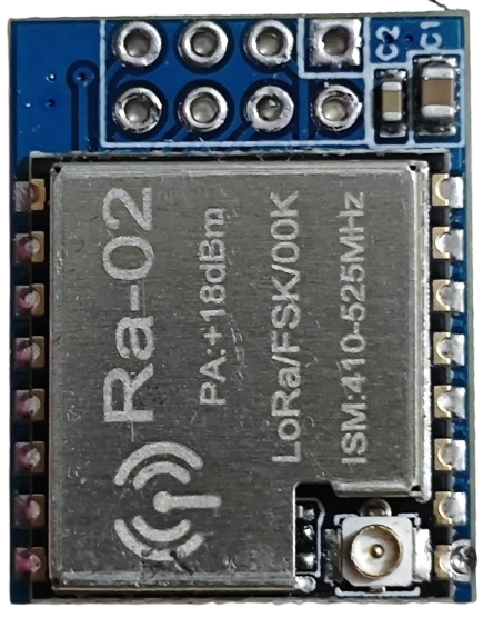
The LoRa RA-02 is a low-power, long-range transceiver module that operates on LoRa (Long Range) modulation technology. It is specifically designed for wireless communication in IoT applications, offering a communication range of up to several kilometers in open areas. The module supports various frequency bands (typically 433 MHz or 868/915 MHz, depending on the region) and is ideal for applications requiring low power consumption and extended range.
Explore Projects Built with lora ra-02

Explore Projects Built with lora ra-02
Common Applications
- Remote sensor networks
- Smart agriculture and environmental monitoring
- Industrial automation
- Smart cities and infrastructure
- Asset tracking and logistics
- Home automation and security systems
Technical Specifications
Below are the key technical details of the LoRa RA-02 module:
| Parameter | Value |
|---|---|
| Operating Voltage | 1.8V to 3.7V (typical 3.3V) |
| Operating Current | 10.8 mA (transmit mode), 10.3 mA (receive mode) |
| Sleep Current | < 200 nA |
| Frequency Range | 433 MHz / 868 MHz / 915 MHz (region-specific) |
| Modulation Technology | LoRa (Long Range) |
| Communication Range | Up to 10 km (line of sight) |
| Data Rate | 0.018 kbps to 37.5 kbps |
| Sensitivity | -148 dBm |
| Output Power | Up to +20 dBm |
| Interface | SPI |
| Dimensions | 16 mm x 16 mm |
Pin Configuration and Descriptions
The LoRa RA-02 module has 16 pins. Below is the pinout and description:
| Pin Number | Pin Name | Description |
|---|---|---|
| 1 | GND | Ground |
| 2 | DIO1 | Digital I/O pin 1 (interrupt or status signaling) |
| 3 | DIO2 | Digital I/O pin 2 (interrupt or status signaling) |
| 4 | DIO3 | Digital I/O pin 3 (interrupt or status signaling) |
| 5 | DIO4 | Digital I/O pin 4 (interrupt or status signaling) |
| 6 | DIO5 | Digital I/O pin 5 (interrupt or status signaling) |
| 7 | GND | Ground |
| 8 | ANT | Antenna connection |
| 9 | GND | Ground |
| 10 | MISO | SPI Master In Slave Out |
| 11 | MOSI | SPI Master Out Slave In |
| 12 | SCK | SPI Clock |
| 13 | NSS | SPI Chip Select |
| 14 | RESET | Reset pin (active low) |
| 15 | 3.3V | Power supply (3.3V) |
| 16 | GND | Ground |
Usage Instructions
How to Use the LoRa RA-02 in a Circuit
- Power Supply: Connect the
3.3Vpin to a regulated 3.3V power source. Ensure the power supply can provide sufficient current for the module's operation. - SPI Interface: Connect the
MISO,MOSI,SCK, andNSSpins to the corresponding SPI pins on your microcontroller. - Antenna: Attach a suitable antenna to the
ANTpin for optimal range and performance. - Reset: Use the
RESETpin to initialize the module. This pin is active low. - Digital I/O Pins: Use the
DIOpins for interrupts or status signaling, as required by your application.
Important Considerations
- Voltage Levels: The module operates at 3.3V. If using a 5V microcontroller (e.g., Arduino UNO), use a level shifter for the SPI and control pins.
- Antenna Placement: Ensure the antenna is placed away from other components to avoid interference.
- Regulatory Compliance: Operate the module within the frequency bands and power levels allowed in your region.
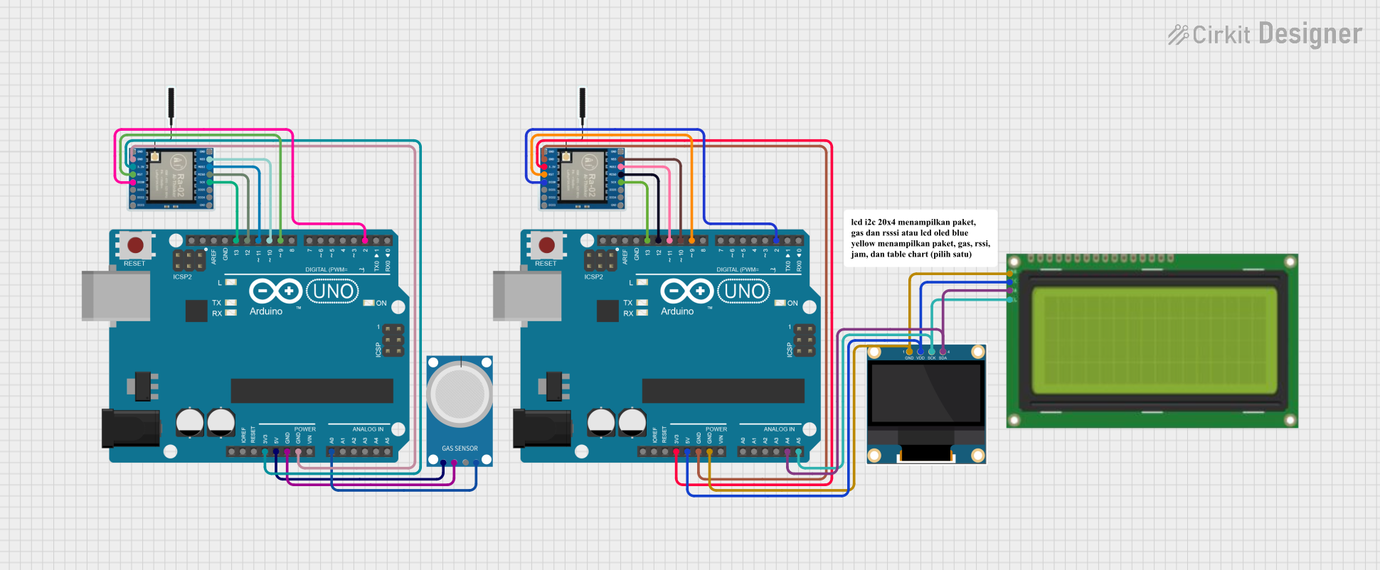
Example: Connecting LoRa RA-02 to Arduino UNO
Below is an example of how to connect the LoRa RA-02 module to an Arduino UNO using the SPI interface:
| LoRa RA-02 Pin | Arduino UNO Pin |
|---|---|
| MISO | Pin 12 |
| MOSI | Pin 11 |
| SCK | Pin 13 |
| NSS | Pin 10 |
| RESET | Pin 9 |
| 3.3V | 3.3V |
| GND | GND |
Example Code
The following Arduino code demonstrates basic communication with the LoRa RA-02 module using the LoRa library:
#include <SPI.h>
#include <LoRa.h>

// Define LoRa module pins
#define NSS 10
#define RESET 9
#define DIO0 2

void setup() {
  // Initialize serial communication
  Serial.begin(9600);
  while (!Serial);

  // Initialize LoRa module
  Serial.println("Initializing LoRa...");
  if (!LoRa.begin(915E6)) { // Set frequency to 915 MHz
    Serial.println("LoRa initialization failed!");
    while (1);
  }
  Serial.println("LoRa initialized successfully.");
}

void loop() {
  // Send a test message
  Serial.println("Sending message...");
  LoRa.beginPacket();
  LoRa.print("Hello, LoRa!");
  LoRa.endPacket();

  // Wait for 5 seconds before sending the next message
  delay(5000);
}
Notes:
- Replace
915E6with the appropriate frequency for your region (e.g.,433E6or868E6). - Ensure the
LoRalibrary is installed in your Arduino IDE.
Troubleshooting and FAQs
Common Issues
Module Not Responding:
- Ensure the power supply is stable and provides 3.3V.
- Verify the SPI connections and pin assignments in the code.
Poor Communication Range:
- Check the antenna connection and placement.
- Ensure there are no significant obstacles or interference sources.
LoRa Initialization Fails:
- Confirm the frequency setting matches the module's supported frequency.
- Verify the
RESETpin is properly connected.
FAQs
Q: Can I use the LoRa RA-02 module with a 5V microcontroller?
A: Yes, but you must use a level shifter for the SPI and control pins, as the module operates at 3.3V.
Q: What is the maximum range of the LoRa RA-02 module?
A: The range can reach up to 10 km in open areas with a clear line of sight. However, obstacles and interference can reduce the range.
Q: Do I need an external antenna?
A: Yes, an external antenna is required for optimal performance. Ensure the antenna matches the operating frequency of the module.
Q: Can multiple LoRa modules communicate with each other?
A: Yes, multiple LoRa modules can communicate as long as they are configured to use the same frequency, spreading factor, and other communication parameters.