How to Use Arduino Mega Terminal Board: Examples, Pinouts, and Specs
Introduction
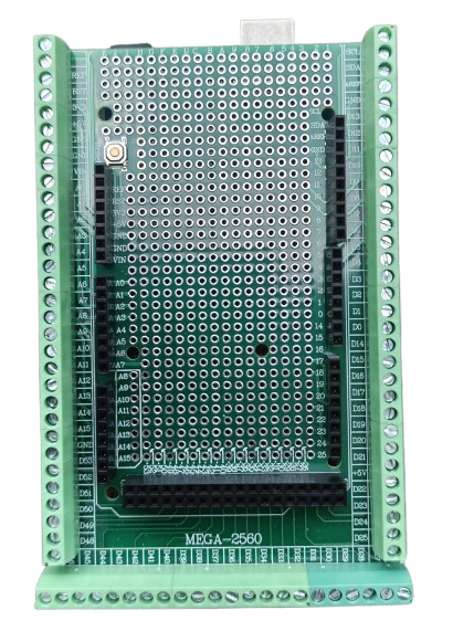
The Arduino Mega Terminal Board is a prototyping accessory designed specifically for the Arduino Mega microcontroller board. It provides a convenient way to access all the pins of the Arduino Mega via screw terminals, making it easier to connect external components, sensors, and modules. This terminal board is ideal for prototyping, testing, and building robust circuits without the need for soldering or breadboards.
Explore Projects Built with Arduino Mega Terminal Board
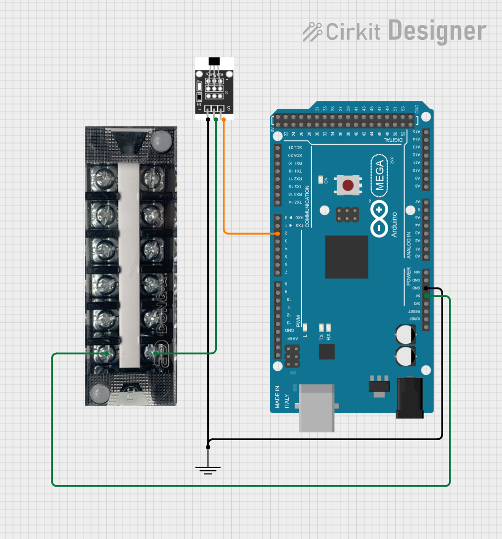

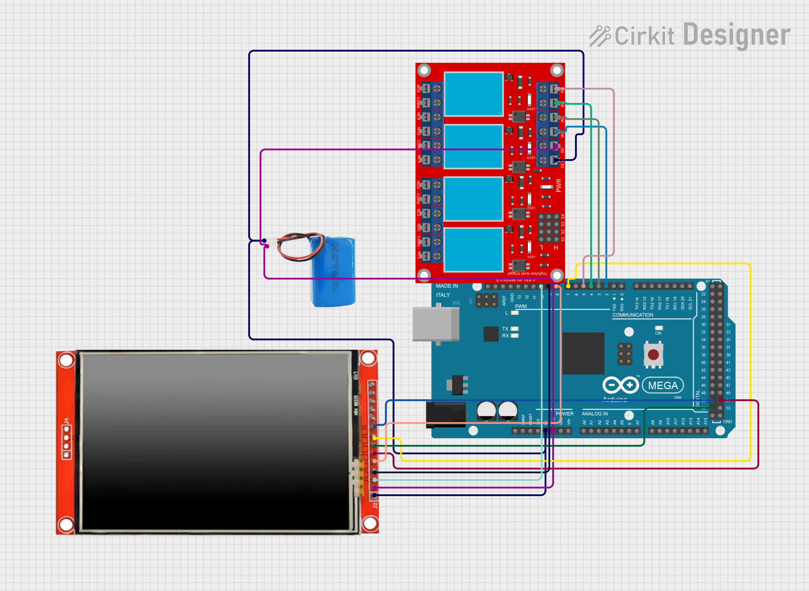

Explore Projects Built with Arduino Mega Terminal Board
Common Applications and Use Cases
- Rapid prototyping of circuits with the Arduino Mega.
- Building robust and secure connections for long-term projects.
- Educational purposes, allowing students to easily connect and test components.
- Industrial applications where secure wiring is required.
- Projects requiring frequent reconfiguration of connections.
Technical Specifications
Below are the key technical details of the Arduino Mega Terminal Board:
| Specification | Details |
|---|---|
| Manufacturer | Arduino |
| Manufacturer Part ID | Mega |
| Compatible Boards | Arduino Mega 2560, Arduino Mega ADK |
| Dimensions | Matches the Arduino Mega form factor |
| Terminal Type | Screw terminals for secure connections |
| Pin Access | All Arduino Mega pins (digital, analog, power, and communication) exposed |
| Power Input | Supports 5V and 3.3V logic levels |
| Material | High-quality PCB with labeled pin headers |
| Mounting Holes | Pre-drilled holes for secure mounting |
Pin Configuration and Descriptions
The Arduino Mega Terminal Board provides access to all the pins of the Arduino Mega. Below is a table summarizing the pin groups and their descriptions:
| Pin Group | Description |
|---|---|
| Digital Pins (0-53) | General-purpose digital I/O pins. Pins 0 and 1 are used for serial communication. |
| Analog Pins (A0-A15) | Analog input pins for reading sensor data or other analog signals. |
| Power Pins | Includes 5V, 3.3V, and GND for powering external components. |
| Communication Pins | Includes I2C (SDA, SCL), SPI (MISO, MOSI, SCK), and UART (TX, RX) pins. |
| Reset Pin | Allows manual resetting of the Arduino Mega. |
Usage Instructions
How to Use the Arduino Mega Terminal Board in a Circuit
- Attach the Arduino Mega: Securely mount the Arduino Mega onto the terminal board by aligning the pins and pressing it into the headers.
- Connect Components: Use the screw terminals to connect external components, such as sensors, motors, or LEDs, to the corresponding pins.
- Power the Board: Provide power to the Arduino Mega through the USB port or an external power supply.
- Upload Code: Write and upload your Arduino sketch using the Arduino IDE.
- Test Connections: Verify that all connections are secure and that the circuit functions as expected.
Important Considerations and Best Practices
- Avoid Over-tightening: When using the screw terminals, avoid over-tightening the screws to prevent damage to the terminals or wires.
- Check Pin Labels: Ensure that you connect components to the correct pins by referring to the labeled pin headers on the terminal board.
- Power Supply: Use a stable power supply to avoid voltage fluctuations that could damage the Arduino Mega or connected components.
- Avoid Short Circuits: Double-check all connections to ensure there are no short circuits between adjacent terminals.
- Use Proper Wire Gauge: Use wires of appropriate gauge for the current requirements of your circuit.
Example: Connecting an LED to Digital Pin 13
Below is an example of how to connect an LED to digital pin 13 using the Arduino Mega Terminal Board and control it with a simple sketch.
Circuit Setup
- Connect the positive leg (anode) of the LED to the screw terminal corresponding to digital pin 13.
- Connect the negative leg (cathode) of the LED to a GND terminal.
- Optionally, place a 220-ohm resistor in series with the LED to limit current.
Arduino Code
// This sketch blinks an LED connected to digital pin 13 on the Arduino Mega Terminal Board.

void setup() {
  pinMode(13, OUTPUT); // Set pin 13 as an output pin
}

void loop() {
  digitalWrite(13, HIGH); // Turn the LED on
  delay(1000);            // Wait for 1 second
  digitalWrite(13, LOW);  // Turn the LED off
  delay(1000);            // Wait for 1 second
}
Troubleshooting and FAQs
Common Issues and Solutions
Problem: The connected components are not functioning.
- Solution: Verify that the components are connected to the correct pins and that the screw terminals are tightened securely.
Problem: The Arduino Mega is not powering on.
- Solution: Check the power supply connection and ensure that the board is receiving the correct voltage.
Problem: Short circuits between adjacent terminals.
- Solution: Inspect the wiring and ensure that no exposed wires are touching each other.
Problem: The uploaded sketch is not working as expected.
- Solution: Double-check the code for errors and ensure that the correct pins are defined in the sketch.
FAQs
Q: Can I use the terminal board with other Arduino boards?
A: No, the terminal board is specifically designed for the Arduino Mega and is not compatible with other Arduino models.
Q: What is the maximum wire gauge supported by the screw terminals?
A: The screw terminals typically support wire gauges ranging from 22 AWG to 16 AWG.
Q: Can I use the terminal board for high-current applications?
A: The terminal board is designed for low-current applications. For high-current circuits, use appropriate relays or external power supplies.
Q: Is the terminal board stackable with other shields?
A: No, the terminal board is not stackable as it is designed to provide direct access to the Arduino Mega pins.
By following this documentation, you can effectively use the Arduino Mega Terminal Board for your prototyping and testing needs.