How to Use RP3 Receiver: Examples, Pinouts, and Specs
Introduction
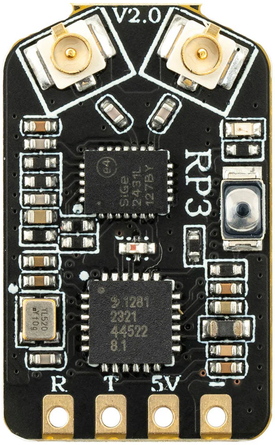
The RP3 Receiver by RadioMaster (Part ID: RP3) is a high-performance radio receiver designed to operate within the RP3 frequency band. It is widely used in communication systems, remote control applications, and wireless data transmission. The RP3 Receiver is known for its reliability, compact design, and ease of integration into various electronic systems.
Explore Projects Built with RP3 Receiver


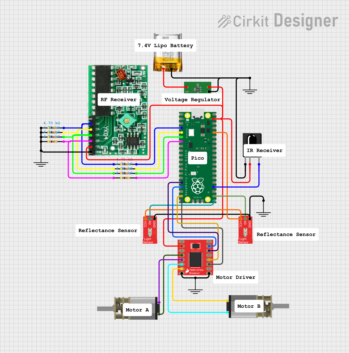

Explore Projects Built with RP3 Receiver
Common Applications
- Remote-controlled devices (e.g., drones, cars, and boats)
- Wireless communication systems
- IoT (Internet of Things) devices
- Data acquisition and telemetry systems
- Industrial automation and control
Technical Specifications
The following table outlines the key technical details of the RP3 Receiver:
| Parameter | Value |
|---|---|
| Operating Frequency | RP3 Band (2.4 GHz) |
| Input Voltage Range | 3.3V to 5.5V |
| Current Consumption | 30 mA (typical) |
| Communication Protocol | PWM, SBUS, or PPM |
| Operating Temperature | -20°C to +70°C |
| Dimensions | 25 mm x 15 mm x 5 mm |
| Weight | 5 grams |
| Sensitivity | -97 dBm |
| Antenna Connector | U.FL or soldered wire |
Pin Configuration
The RP3 Receiver has a simple pinout for easy integration. The pin configuration is as follows:
| Pin Number | Pin Name | Description |
|---|---|---|
| 1 | VCC | Power supply input (3.3V to 5.5V) |
| 2 | GND | Ground |
| 3 | Signal Out | Output signal (PWM, SBUS, or PPM) |
| 4 | Bind | Binding button for pairing with a transmitter |
Usage Instructions
How to Use the RP3 Receiver in a Circuit
- Power Supply: Connect the VCC pin to a regulated power source (3.3V to 5.5V) and the GND pin to the ground of your circuit.
- Signal Output: Connect the Signal Out pin to the input of your microcontroller or servo motor, depending on your application.
- Binding: To pair the RP3 Receiver with a compatible transmitter:
- Press and hold the Bind button while powering on the receiver.
- Follow the transmitter's binding procedure to establish a connection.
- Once paired, the receiver will automatically reconnect to the transmitter on subsequent power-ups.
- Antenna: Ensure the antenna is securely connected to the U.FL connector or soldered properly for optimal signal reception.
Important Considerations and Best Practices
- Power Supply: Use a stable and noise-free power source to avoid interference.
- Antenna Placement: Position the antenna away from metal objects or other electronic components to minimize signal degradation.
- Signal Protocol: Ensure your microcontroller or device supports the selected communication protocol (PWM, SBUS, or PPM).
- Environment: Avoid operating the receiver in environments with excessive RF interference or extreme temperatures.
Example: Connecting RP3 Receiver to Arduino UNO
The RP3 Receiver can be easily interfaced with an Arduino UNO using the PWM protocol. Below is an example code snippet to read the PWM signal:
// Example code to read PWM signal from RP3 Receiver using Arduino UNO

const int signalPin = 2; // Connect Signal Out pin of RP3 Receiver to Arduino pin 2
volatile unsigned long pulseWidth = 0; // Variable to store pulse width
volatile unsigned long lastTime = 0;  // Variable to store the last interrupt time

void setup() {
  pinMode(signalPin, INPUT); // Set signal pin as input
  Serial.begin(9600);        // Initialize serial communication
  attachInterrupt(digitalPinToInterrupt(signalPin), readPulse, CHANGE);
  // Attach interrupt to signal pin to detect pulse changes
}

void loop() {
  // Print the pulse width in microseconds
  Serial.print("Pulse Width: ");
  Serial.print(pulseWidth);
  Serial.println(" us");
  delay(500); // Delay for readability
}

void readPulse() {
  if (digitalRead(signalPin) == HIGH) {
    // If signal goes HIGH, record the current time
    lastTime = micros();
  } else {
    // If signal goes LOW, calculate the pulse width
    pulseWidth = micros() - lastTime;
  }
}
Notes:
- Ensure the RP3 Receiver is properly bound to a transmitter before running the code.
- The
signalPinin the code should match the Arduino pin connected to the Signal Out pin of the receiver.
Troubleshooting and FAQs
Common Issues and Solutions
No Signal Output
- Cause: The receiver is not bound to the transmitter.
- Solution: Follow the binding procedure outlined in the usage instructions.
Intermittent Signal Loss
- Cause: Poor antenna placement or RF interference.
- Solution: Reposition the antenna and ensure it is not obstructed by metal objects.
Receiver Overheating
- Cause: Operating outside the recommended voltage range.
- Solution: Verify the power supply voltage is within the 3.3V to 5.5V range.
Signal Protocol Mismatch
- Cause: The connected device does not support the selected protocol.
- Solution: Configure the receiver and device to use a compatible protocol (PWM, SBUS, or PPM).
FAQs
Q: Can the RP3 Receiver operate with a 3.3V microcontroller?
A: Yes, the RP3 Receiver is compatible with 3.3V systems, as its input voltage range is 3.3V to 5.5V.
Q: How do I know if the receiver is successfully bound to the transmitter?
A: Most transmitters and receivers have an LED indicator. A solid LED on the receiver typically indicates a successful bind.
Q: Can I use the RP3 Receiver for long-range communication?
A: The RP3 Receiver is designed for short to medium-range communication. For long-range applications, consider using a receiver with extended range capabilities.
Q: What should I do if the receiver stops working after a firmware update?
A: Ensure the firmware update is compatible with the RP3 Receiver. If issues persist, contact RadioMaster support for assistance.
By following this documentation, users can effectively integrate and troubleshoot the RP3 Receiver in their projects.