How to Use Raspberry Pi 5: Examples, Pinouts, and Specs
Introduction
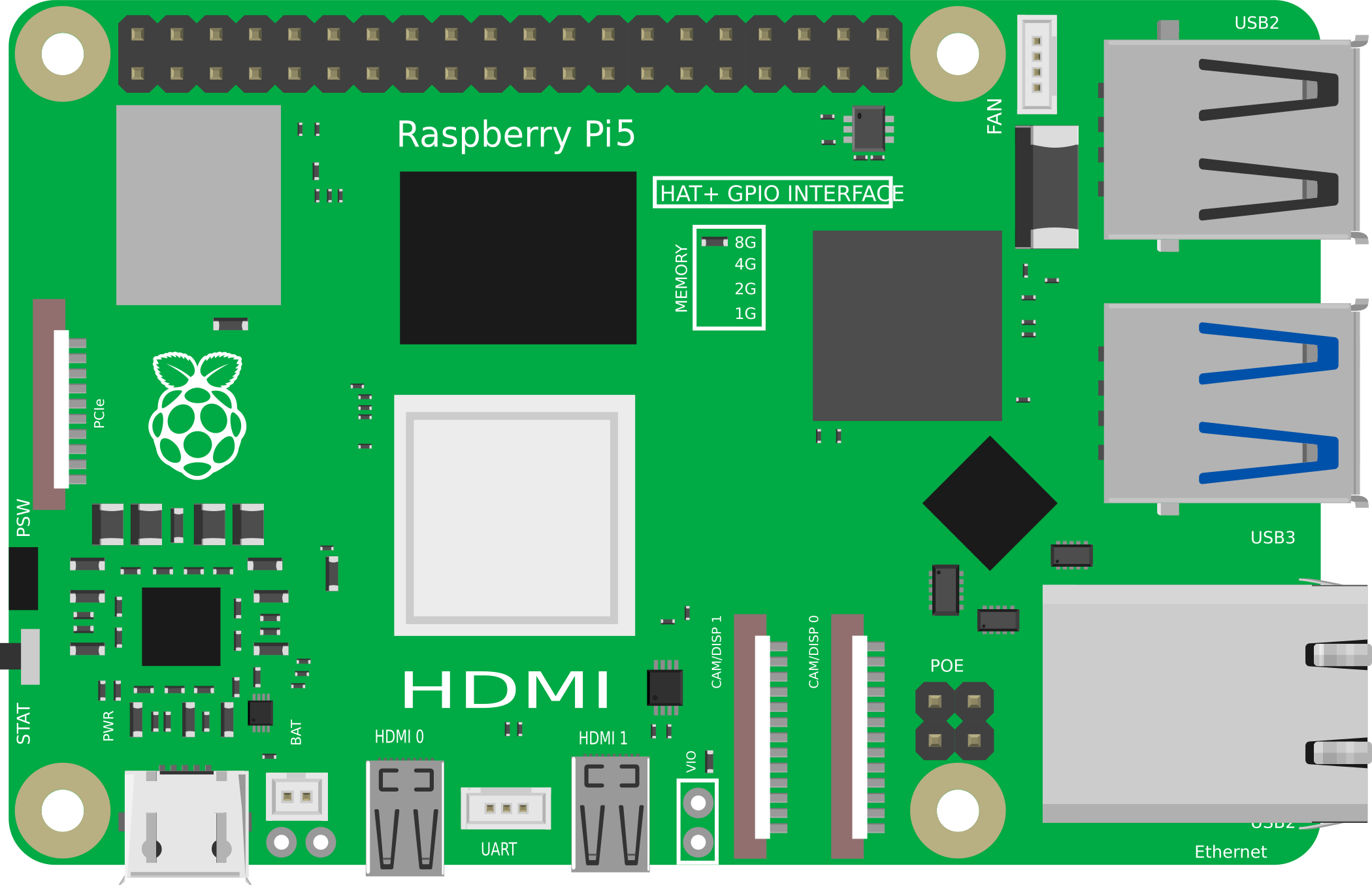
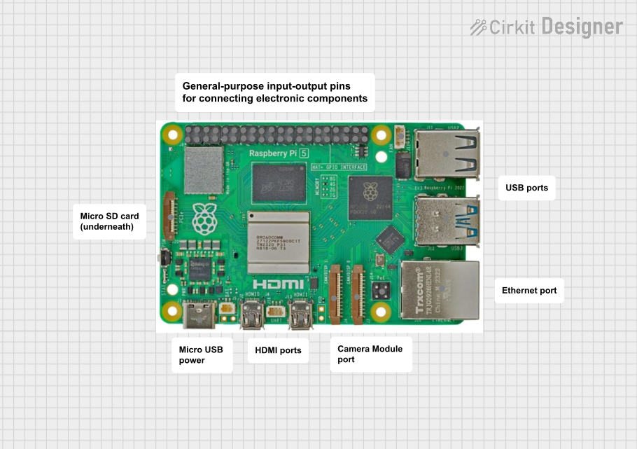
The Raspberry Pi 5 is a compact, affordable single-board computer designed for a wide range of applications. It features a powerful quad-core processor, multiple USB ports, HDMI output, and GPIO pins, making it an excellent choice for programming, robotics, IoT, and other electronic projects. Its versatility and affordability have made it a popular tool for hobbyists, educators, and professionals alike.
Explore Projects Built with Raspberry Pi 5
Explore Projects Built with Raspberry Pi 5
Common Applications and Use Cases
- Programming and Software Development: Ideal for learning programming languages like Python, C++, and Java.
- IoT Projects: Used to create smart home devices, sensors, and automation systems.
- Robotics: Serves as the brain for robots, enabling control and data processing.
- Media Centers: Can be configured as a media player or streaming device.
- Educational Tools: Widely used in schools and universities for teaching computing and electronics.
Technical Specifications
The Raspberry Pi 5 offers significant improvements over its predecessors, providing enhanced performance and connectivity.
Key Technical Details
- Processor: Quad-core ARM Cortex-A76, 2.4 GHz
- RAM: 4GB or 8GB LPDDR4X (depending on the model)
- Storage: MicroSD card slot, support for external SSDs via USB 3.0
- USB Ports: 2 × USB 3.0, 2 × USB 2.0
- HDMI Output: Dual micro-HDMI ports, supporting up to 4K resolution at 60Hz
- Networking: Gigabit Ethernet, Wi-Fi 6, Bluetooth 5.2
- GPIO Pins: 40-pin header, compatible with HATs and other accessories
- Power Supply: USB-C, 5V/3A
- Dimensions: 85.6mm × 56.5mm × 17mm
Pin Configuration and Descriptions
The Raspberry Pi 5 features a 40-pin GPIO header for interfacing with external components. Below is the pinout:
| Pin Number | Pin Name | Function |
|---|---|---|
| 1 | 3.3V | Power supply (3.3V) |
| 2 | 5V | Power supply (5V) |
| 3 | GPIO2 (SDA1) | I2C Data Line |
| 4 | 5V | Power supply (5V) |
| 5 | GPIO3 (SCL1) | I2C Clock Line |
| 6 | GND | Ground |
| 7 | GPIO4 | General Purpose I/O |
| 8 | GPIO14 (TXD) | UART Transmit |
| 9 | GND | Ground |
| 10 | GPIO15 (RXD) | UART Receive |
| ... | ... | ... |
| 39 | GND | Ground |
| 40 | GPIO21 | General Purpose I/O |
For a complete pinout diagram, refer to the official Raspberry Pi documentation.
Usage Instructions
How to Use the Raspberry Pi 5 in a Circuit
- Powering the Raspberry Pi: Use a 5V/3A USB-C power adapter to power the board.
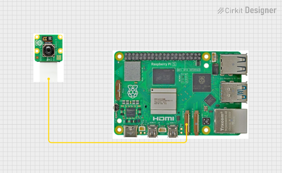
- Connecting Peripherals: Attach a monitor via the micro-HDMI port, a keyboard and mouse via USB, and a microSD card with the operating system installed.
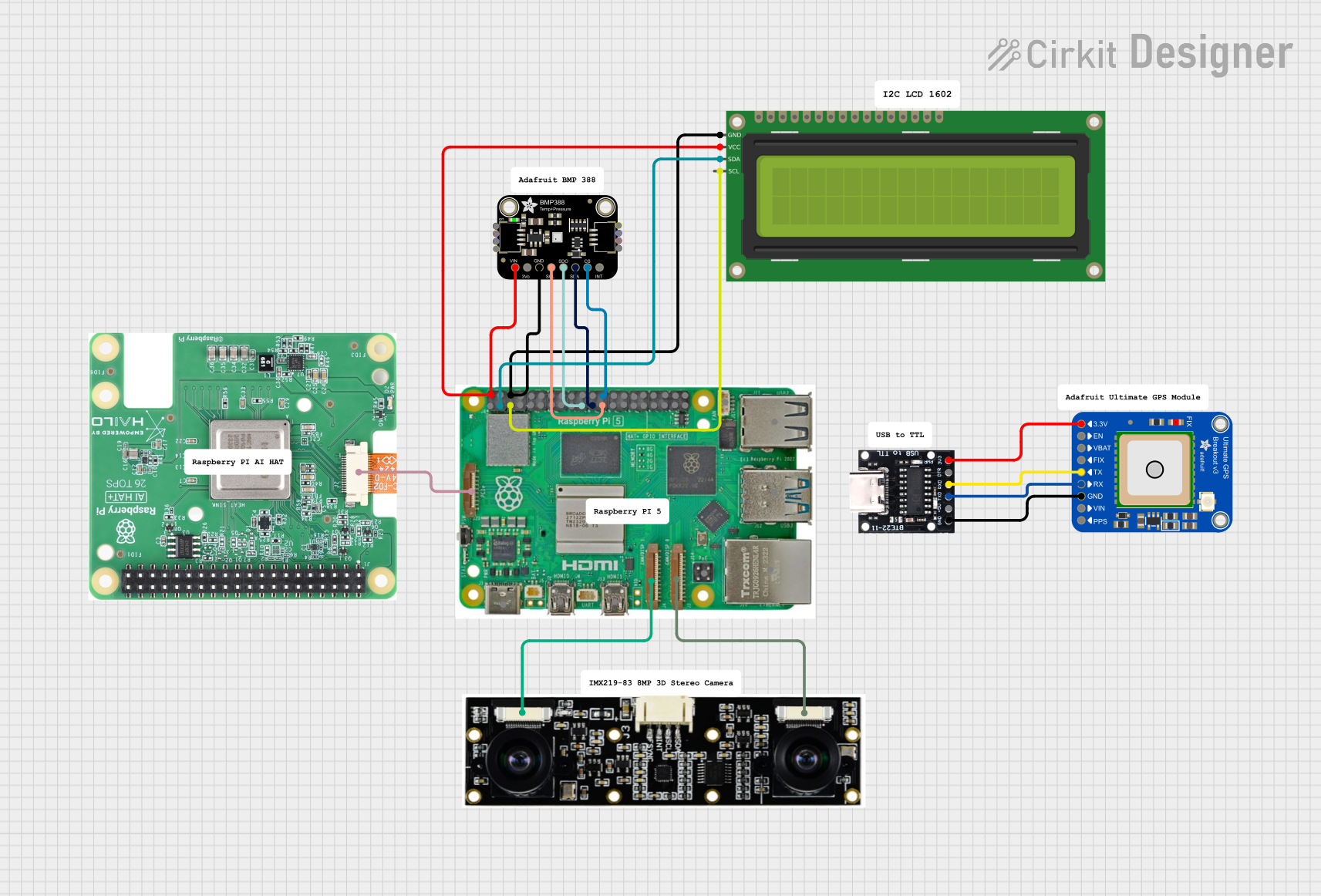
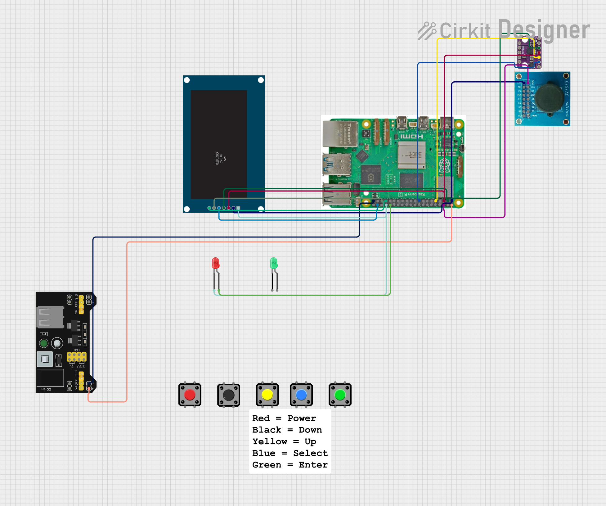
- Using GPIO Pins: Connect external components (e.g., LEDs, sensors) to the GPIO pins. Use a breadboard and jumper wires for prototyping.
- Networking: Connect to the internet via Ethernet or Wi-Fi for software updates and remote access.
Important Considerations and Best Practices
- Static Protection: Handle the board carefully to avoid static discharge, which can damage components.
- Cooling: Use a heatsink or fan for cooling during intensive tasks to prevent overheating.
- Power Supply: Ensure the power supply meets the required specifications to avoid instability.
- GPIO Safety: Avoid exceeding the voltage and current limits of the GPIO pins (3.3V logic level).
Example: Blinking an LED with GPIO and Python
The following example demonstrates how to blink an LED connected to GPIO pin 17 using Python.
Circuit Setup
- Connect the positive leg of the LED to GPIO pin 17.
- Connect the negative leg of the LED to a 330-ohm resistor, and then to a GND pin.
Code
Import the GPIO library and time module
import RPi.GPIO as GPIO import time
Set up GPIO mode
GPIO.setmode(GPIO.BCM) # Use Broadcom pin numbering GPIO.setup(17, GPIO.OUT) # Set GPIO 17 as an output pin
try: while True: GPIO.output(17, GPIO.HIGH) # Turn on the LED time.sleep(1) # Wait for 1 second GPIO.output(17, GPIO.LOW) # Turn off the LED time.sleep(1) # Wait for 1 second except KeyboardInterrupt: # Clean up GPIO settings on exit GPIO.cleanup()
Troubleshooting and FAQs
Common Issues and Solutions
The Raspberry Pi does not boot:
- Ensure the microSD card is properly inserted and contains a valid operating system image.
- Check the power supply for proper voltage and current output.
No display on the monitor:
- Verify the HDMI cable is securely connected.
- Ensure the monitor is set to the correct input source.
- Check the configuration file (
config.txt) on the microSD card for display settings.
GPIO pins not working:
- Confirm the correct pin numbering mode (BCM or BOARD) is used in the code.
- Check for loose connections or damaged components in the circuit.
Overheating:
- Use a heatsink or fan to improve cooling.
- Avoid running resource-intensive tasks for extended periods without proper cooling.
FAQs
Can I use the Raspberry Pi 5 with older HATs and accessories? Yes, the GPIO header is backward-compatible with previous Raspberry Pi models.
What operating systems are supported? The Raspberry Pi 5 supports Raspberry Pi OS, Ubuntu, and other Linux-based distributions.
Can I power the Raspberry Pi 5 via GPIO pins? Yes, but it is recommended to use the USB-C port for stable power delivery.
How do I enable SSH for remote access? Create an empty file named
sshin the boot partition of the microSD card before booting the Raspberry Pi.