
How to Use PCM1803: Examples, Pinouts, and Specs
 Design with PCM1803 in Cirkit Designer
Introduction
The PCM1803, manufactured by Texas Instruments, is a high-performance, 24-bit audio analog-to-digital converter (ADC) designed for high-fidelity audio applications. It offers a low noise floor, high dynamic range, and supports multiple audio sampling rates, making it ideal for professional audio equipment, consumer electronics, and other audio processing systems.
Explore Projects Built with PCM1803
 Open Project in Cirkit Designer
 Open Project in Cirkit Designer
 Open Project in Cirkit Designer
 Open Project in Cirkit Designer
Explore Projects Built with PCM1803
Open Project in Cirkit DesignerOpen Project in Cirkit DesignerOpen Project in Cirkit DesignerOpen Project in Cirkit DesignerCommon Applications
- Professional audio recording equipment
- Consumer audio devices (e.g., home theater systems, audio interfaces)
- Musical instruments with digital output
- Audio signal processing systems
- Voice recognition and audio analysis systems
Technical Specifications
Key Technical Details
- Resolution: 24-bit
- Dynamic Range: 103 dB (typical)
- Signal-to-Noise Ratio (SNR): 103 dB (typical)
- Total Harmonic Distortion + Noise (THD+N): -93 dB (typical)
- Sampling Rates: 16 kHz to 96 kHz
- Input Voltage Range: 0.6 Vpp to 2.1 Vpp (differential)
- Power Supply Voltage:
- Analog: 5 V
- Digital: 3.3 V
- Power Consumption: 85 mW (typical)
- Operating Temperature Range: -25°C to 85°C
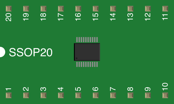
- Package: 20-pin SSOP (Shrink Small Outline Package)
Pin Configuration and Descriptions
The PCM1803 comes in a 20-pin SSOP package. Below is the pin configuration and description:
| Pin Number | Pin Name | Type | Description |
|---|---|---|---|
| 1 | VINL | Analog Input | Left-channel analog input (differential positive) |
| 2 | VINR | Analog Input | Right-channel analog input (differential positive) |
| 3 | VCOM | Analog Output | Common voltage output for decoupling |
| 4 | AGND | Ground | Analog ground |
| 5 | VCC | Power Supply | Analog power supply (5 V) |
| 6 | FMT0 | Digital Input | Audio data format selection (bit 0) |
| 7 | FMT1 | Digital Input | Audio data format selection (bit 1) |
| 8 | SCKI | Digital Input | System clock input |
| 9 | BCK | Digital Input | Audio data bit clock input |
| 10 | LRCK | Digital Input | Audio data word clock input |
| 11 | DOUT | Digital Output | Audio data output |
| 12 | DGND | Ground | Digital ground |
| 13 | VDD | Power Supply | Digital power supply (3.3 V) |
| 14 | PDWN | Digital Input | Power-down control (active low) |
| 15 | BYPAS | Digital Input | Bypass mode control |
| 16 | OSR | Digital Input | Oversampling rate selection |
| 17 | ZCAL | Digital Input | Zero calibration control |
| 18 | TEST | Digital Input | Test mode control (must be tied to DGND for normal operation) |
| 19 | VINL- | Analog Input | Left-channel analog input (differential negative) |
| 20 | VINR- | Analog Input | Right-channel analog input (differential negative) |
Usage Instructions
Using the PCM1803 in a Circuit
Power Supply:
- Connect the analog power supply (5 V) to the
VCCpin and the digital power supply (3.3 V) to theVDDpin. Ensure proper decoupling capacitors are placed close to the power pins. - Connect
AGNDandDGNDto the ground plane of the circuit.
- Connect the analog power supply (5 V) to the
Analog Input:
- Provide differential analog audio signals to the
VINL,VINL-,VINR, andVINR-pins. Use appropriate coupling capacitors to block DC components.
- Provide differential analog audio signals to the
Clock Signals:
- Provide a system clock (SCKI) to the PCM1803. The clock frequency should match the required sampling rate and oversampling ratio.
Audio Data Format:
- Configure the audio data format using the
FMT0andFMT1pins. The PCM1803 supports I2S, left-justified, and right-justified formats.
- Configure the audio data format using the
Audio Data Output:
- Connect the
DOUTpin to the digital audio receiver or microcontroller to capture the audio data.
- Connect the
Power-Down Mode:
- Use the
PDWNpin to enable or disable the power-down mode. Pull the pin low to enter power-down mode.
- Use the
Important Considerations
- Use a low-noise power supply and proper grounding techniques to minimize noise and interference.
- Ensure the system clock (SCKI) is stable and meets the required frequency specifications.
- Avoid leaving unused pins floating; tie them to the appropriate logic level as specified in the datasheet.
- Use high-quality differential amplifiers or preamps to drive the analog inputs for optimal performance.
Example: Connecting PCM1803 to Arduino UNO
The PCM1803 can be interfaced with an Arduino UNO to capture audio data via the I2S protocol. Below is an example Arduino sketch:
#include <I2S.h> // Include the I2S library for audio data handling

void setup() {
  // Initialize serial communication for debugging
  Serial.begin(9600);

  // Initialize I2S in receive mode
  if (!I2S.begin(I2S_PHILIPS_MODE, 44100)) {
    Serial.println("Failed to initialize I2S!");
    while (1); // Halt execution if I2S initialization fails
  }

  Serial.println("I2S initialized successfully.");
}

void loop() {
  // Check if audio data is available
  if (I2S.available()) {
    int sample = I2S.read(); // Read a 16-bit audio sample
    Serial.println(sample);  // Print the sample to the serial monitor
  }
}
Notes:
- Ensure the Arduino UNO is connected to the PCM1803's
DOUT,BCK, andLRCKpins. - The I2S library is required for this example. Install it via the Arduino Library Manager if not already installed.
Troubleshooting and FAQs
Common Issues
No Audio Output:
- Verify that the system clock (SCKI) is correctly configured and stable.
- Check the power supply connections and ensure proper decoupling.
Distorted Audio:
- Ensure the analog input signals are within the specified voltage range.
- Verify that the audio data format matches the receiver's configuration.
PCM1803 Not Responding:
- Confirm that the
PDWNpin is pulled high for normal operation. - Check all connections, especially the clock and data lines.
- Confirm that the
FAQs
Q: Can the PCM1803 operate with a single-ended input?
A: No, the PCM1803 requires differential analog inputs for optimal performance. Use a differential amplifier to convert single-ended signals to differential.
Q: What is the maximum sampling rate supported by the PCM1803?
A: The PCM1803 supports sampling rates up to 96 kHz.
Q: How do I select the audio data format?
A: Use the FMT0 and FMT1 pins to configure the desired audio data format. Refer to the datasheet for the pin settings.
Q: Can I use the PCM1803 with a 3.3 V analog power supply?
A: No, the analog power supply (VCC) must be 5 V. The digital power supply (VDD) operates at 3.3 V.
By following this documentation, users can effectively integrate the PCM1803 into their audio systems and troubleshoot common issues.