
How to Use Aux Port: Examples, Pinouts, and Specs
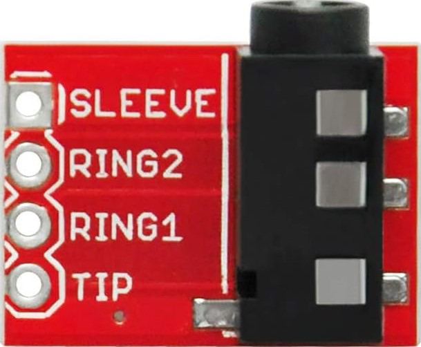
 Design with Aux Port in Cirkit Designer
Introduction
The Aux Port, also known as the auxiliary port, is a 3.5mm audio connector commonly used for transmitting sound between devices. It serves as a universal interface for audio input and output, enabling seamless connectivity between devices such as smartphones, headphones, speakers, and car audio systems. The Aux Port is widely recognized for its simplicity, reliability, and compatibility with a broad range of audio equipment.
Explore Projects Built with Aux Port
 Open Project in Cirkit Designer
 Open Project in Cirkit Designer
 Open Project in Cirkit Designer
 Open Project in Cirkit Designer
Explore Projects Built with Aux Port
Open Project in Cirkit DesignerOpen Project in Cirkit DesignerOpen Project in Cirkit DesignerOpen Project in Cirkit DesignerCommon Applications and Use Cases
- Connecting smartphones or MP3 players to car audio systems.
- Transmitting audio from laptops or PCs to external speakers.
- Connecting headphones or earphones to audio devices.
- Bridging audio signals between mixers, amplifiers, and recording equipment.
Technical Specifications
The Aux Port is a passive component with no active electronic circuitry. Its specifications are primarily mechanical and electrical, ensuring compatibility with standard 3.5mm audio jacks.
Key Technical Details
- Connector Type: 3.5mm TRS (Tip-Ring-Sleeve) or TRRS (Tip-Ring-Ring-Sleeve)
- Audio Channels: Stereo (Left and Right) or Mono
- Impedance: Typically 32Ω to 600Ω (depends on connected devices)
- Voltage Range: 0.5V to 2V (line-level audio signals)
- Material: Gold-plated or nickel-plated contacts for corrosion resistance
- Durability: Rated for thousands of insertion/removal cycles
Pin Configuration and Descriptions
The Aux Port typically supports two configurations: TRS (Tip-Ring-Sleeve) for stereo audio and TRRS (Tip-Ring-Ring-Sleeve) for stereo audio with an additional microphone channel.
TRS Configuration
| Pin Name | Position | Description |
|---|---|---|
| Tip | 1 | Left audio channel |
| Ring | 2 | Right audio channel |
| Sleeve | 3 | Ground (common return path) |
TRRS Configuration
| Pin Name | Position | Description |
|---|---|---|
| Tip | 1 | Left audio channel |
| Ring 1 | 2 | Right audio channel |
| Ring 2 | 3 | Microphone input (optional) |
| Sleeve | 4 | Ground (common return path) |
Usage Instructions
How to Use the Aux Port in a Circuit
- Connect the Aux Port to the Audio Source:
- Insert a 3.5mm audio jack into the Aux Port.
- Ensure the jack is fully seated to avoid poor connections or signal loss.
- Connect the Other End to the Audio Output Device:
- For example, connect the other end of the cable to headphones, speakers, or an amplifier.
- Verify Signal Transmission:
- Play audio from the source device and confirm that the output device receives the signal.
Important Considerations and Best Practices
- Cable Quality: Use high-quality, shielded cables to minimize noise and interference.
- Contact Maintenance: Periodically clean the Aux Port contacts with isopropyl alcohol to prevent oxidation and ensure reliable connections.
- Avoid Excessive Force: Do not apply excessive force when inserting or removing the jack to prevent damage to the port.
- Compatibility Check: Ensure the connected devices support the same pin configuration (TRS or TRRS) to avoid signal mismatches.
Example: Connecting an Aux Port to an Arduino UNO
While the Aux Port is primarily used for audio, it can also be used to transmit analog signals to an Arduino UNO for audio processing or signal analysis. Below is an example of reading an audio signal from an Aux Port using the Arduino's analog input.
// Example: Reading audio signal from an Aux Port using Arduino UNO
// Connect the Aux Port's Tip (Left channel) to A0, and Sleeve (Ground) to GND.

const int audioPin = A0;  // Analog pin connected to the Aux Port's Tip
int audioValue = 0;       // Variable to store the audio signal value

void setup() {
  Serial.begin(9600);  // Initialize serial communication for debugging
}

void loop() {
  audioValue = analogRead(audioPin);  // Read the audio signal
  Serial.println(audioValue);        // Print the signal value to the Serial Monitor
  delay(10);                         // Small delay for stability
}
Note: The Arduino UNO can only read analog signals in the range of 0-5V. If the audio signal exceeds this range, use a voltage divider or coupling capacitor to protect the microcontroller.
Troubleshooting and FAQs
Common Issues Users Might Face
No Audio Output:
- Cause: Loose connection or incompatible pin configuration.
- Solution: Ensure the audio jack is fully inserted and verify the pin configuration (TRS vs. TRRS).
Static or Noise in Audio:
- Cause: Poor cable quality or dirty contacts.
- Solution: Use shielded cables and clean the Aux Port contacts with isopropyl alcohol.
Audio Only on One Channel:
- Cause: Faulty cable or improper connection.
- Solution: Test with a different cable and ensure proper seating of the jack.
Microphone Not Working (TRRS Configuration):
- Cause: Device incompatibility or incorrect wiring.
- Solution: Verify that the connected device supports TRRS and check the wiring.
Solutions and Tips for Troubleshooting
- Test with Known Working Devices: Use a known working audio source and output device to isolate the issue.
- Inspect for Physical Damage: Check the Aux Port and cable for visible damage or wear.
- Use a Multimeter: Measure continuity across the Aux Port pins to ensure proper electrical connections.
By following this documentation, users can effectively utilize the Aux Port for a variety of audio applications while avoiding common pitfalls.