How to Use Adafruit 26-Pin Pi Cobbler: Examples, Pinouts, and Specs
Introduction
The Adafruit 26-Pin Pi Cobbler is an essential breakout kit for Raspberry Pi users who want to bridge the gap between the Pi's GPIO (General Purpose Input/Output) pins and a breadboard for prototyping. This component is particularly useful for hobbyists, educators, and professionals who require an easy and reliable method to connect the Raspberry Pi to a breadboard for developing electronic circuits and exploring new projects.
Explore Projects Built with Adafruit 26-Pin Pi Cobbler


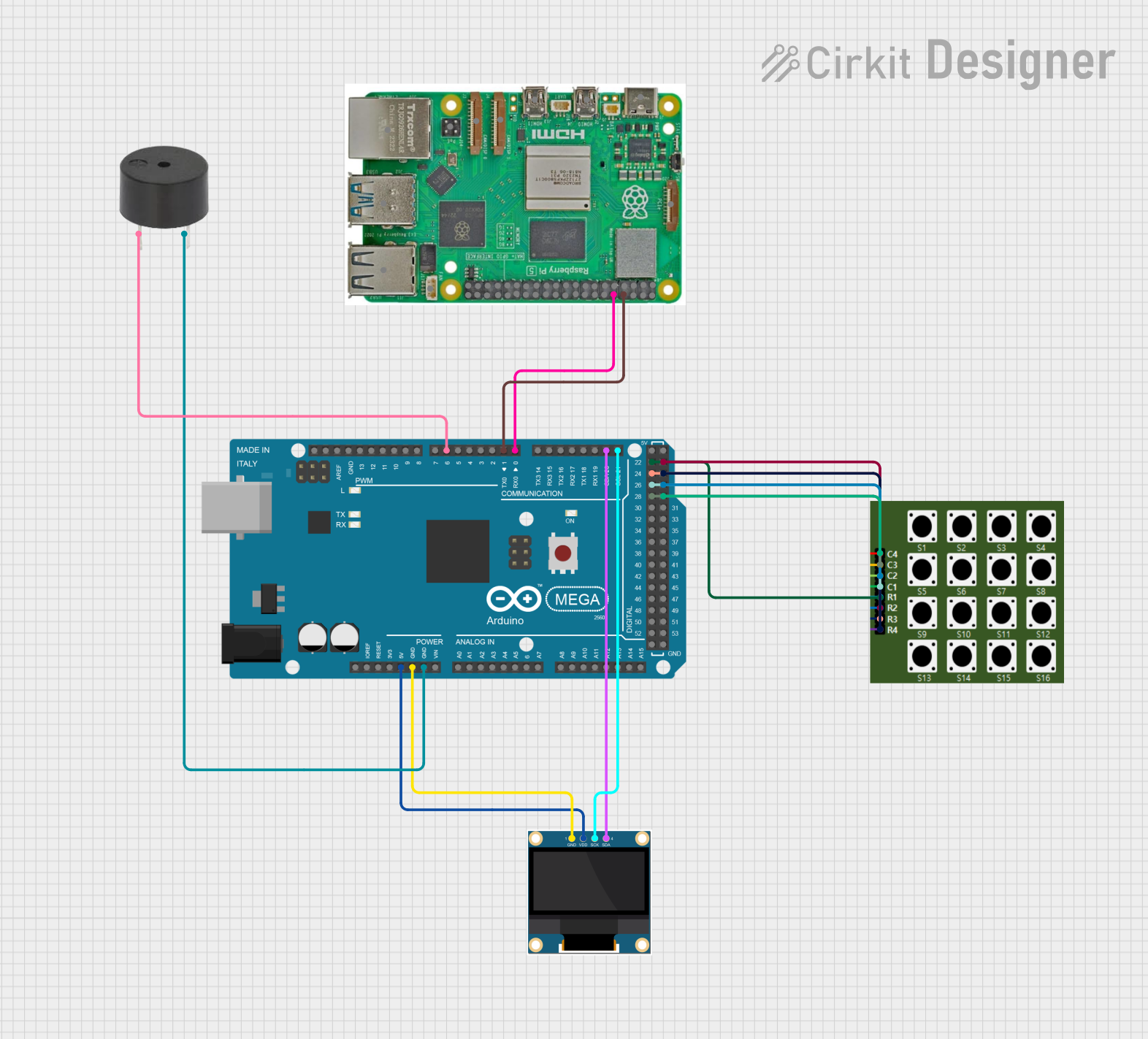
Explore Projects Built with Adafruit 26-Pin Pi Cobbler
Common Applications and Use Cases
- Prototyping electronic circuits
- Educational projects in schools and workshops
- Developing home automation systems
- Creating robotics and IoT (Internet of Things) devices
- Experimenting with digital and analog sensors
Technical Specifications
Key Technical Details
- Compatibility: Designed for Raspberry Pi models with a 26-pin GPIO connector
- Connector Type: 26-pin male header (connects to Raspberry Pi)
- Breadboard Connection: 26-pin female header (for breadboard insertion)
- Dimensions: Typically matches the size of a standard mini breadboard
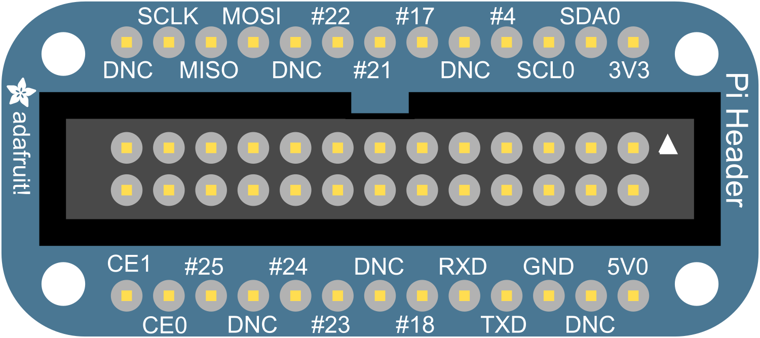
Pin Configuration and Descriptions
| Pin Number | Name | Description |
|---|---|---|
| 1 | 3V3 | 3.3V power rail |
| 2 | 5V | 5V power rail |
| 3 | SDA | I2C data line |
| 4 | 5V | 5V power rail |
| 5 | SCL | I2C clock line |
| 6 | GND | Ground |
| ... | ... | ... |
| 25 | GND | Ground |
| 26 | GPIO7 | General Purpose I/O |
Note: The table above is a partial representation. Refer to the Raspberry Pi GPIO pinout for the complete list.
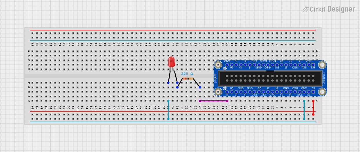
Usage Instructions
How to Use the Component in a Circuit
Connect the Cobbler to the Raspberry Pi:
- Ensure the Raspberry Pi is powered off.
- Align the 26-pin male header of the Pi Cobbler with the GPIO connector on the Raspberry Pi and gently press down to connect.
Insert the Cobbler into a Breadboard:
- Place the 26-pin female header of the Pi Cobbler into the breadboard, ensuring a secure and stable connection.
Wire the Circuit:
- Use jumper wires to connect the desired GPIO pins from the Pi Cobbler to the components on the breadboard.
Power On the Raspberry Pi:
- Once the circuit is set up, power on the Raspberry Pi to start using the GPIO pins with your breadboard circuit.
Important Considerations and Best Practices
- Avoid Hot-Swapping: Never connect or disconnect the Pi Cobbler while the Raspberry Pi is powered on to prevent damage.
- Pin Orientation: Double-check the pin orientation before connecting to avoid incorrect wiring.
- Voltage Levels: Be mindful of the voltage levels; the Raspberry Pi's GPIO pins operate at 3.3V logic levels.
- Current Limitations: Do not draw more than 16 mA from a single GPIO pin and a total of 50 mA from all pins combined.
Troubleshooting and FAQs
Common Issues Users Might Face
- Loose Connections: If the Pi Cobbler is not functioning, check for loose connections between the Raspberry Pi, the Cobbler, and the breadboard.
- Incorrect Wiring: Verify that the wiring matches the intended GPIO pinout.
- Power Issues: Ensure the Raspberry Pi is adequately powered and the power supply is capable of delivering sufficient current.
Solutions and Tips for Troubleshooting
- Re-seat the Cobbler: If connections are loose, power off the Raspberry Pi and re-seat the Cobbler.
- Review Circuit Design: Double-check your circuit design against the schematic or diagram you are following.
- Test GPIO Pins: Use simple test scripts to check if individual GPIO pins are functioning correctly.
FAQs
Q: Can I use the Pi Cobbler with a Raspberry Pi model that has more than 26 GPIO pins? A: The 26-Pin Pi Cobbler is designed for Raspberry Pi models with a 26-pin GPIO connector. For models with a 40-pin GPIO connector, you should use a 40-pin Pi Cobbler.
Q: Is soldering required to use the Pi Cobbler? A: No, the Pi Cobbler is designed to be used without soldering when connecting to a breadboard.
Q: How do I know which GPIO pins to use for my project? A: Refer to the Raspberry Pi GPIO pinout documentation for your specific model to identify the pins you need for your project.
Note: This documentation is provided for informational purposes only. Adafruit Industries and the author are not responsible for any damage to your Raspberry Pi or peripherals due to misuse of the Pi Cobbler.