
How to Use Amphenol ACJS-MHDR 6.35mm Switched Stereo Jack: Examples, Pinouts, and Specs
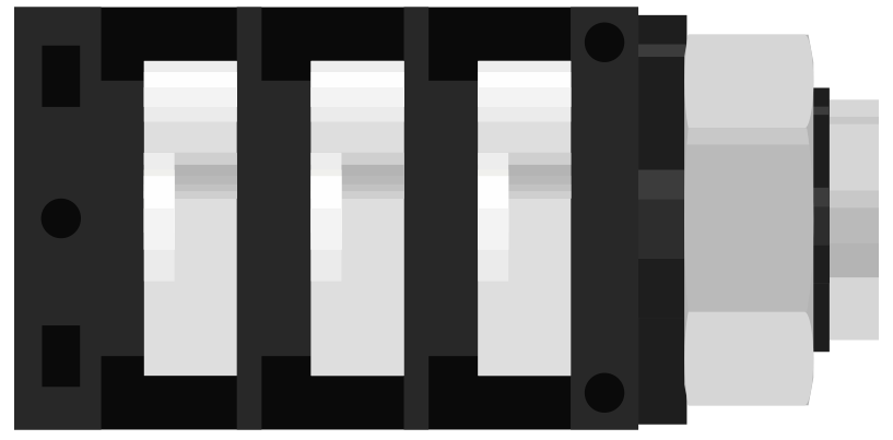
 Design with Amphenol ACJS-MHDR 6.35mm Switched Stereo Jack in Cirkit Designer
Introduction
The Amphenol ACJS-MHDR is a high-quality 6.35mm (1/4 inch) switched stereo jack designed for audio applications. This component is widely used in audio equipment to connect stereo audio signals, such as headphones, amplifiers, and musical instruments. Its built-in switch functionality allows it to control other circuit elements when a plug is inserted, making it a versatile choice for signal routing and control in audio systems.
Explore Projects Built with Amphenol ACJS-MHDR 6.35mm Switched Stereo Jack
 Open Project in Cirkit Designer
 Open Project in Cirkit Designer
 Open Project in Cirkit Designer
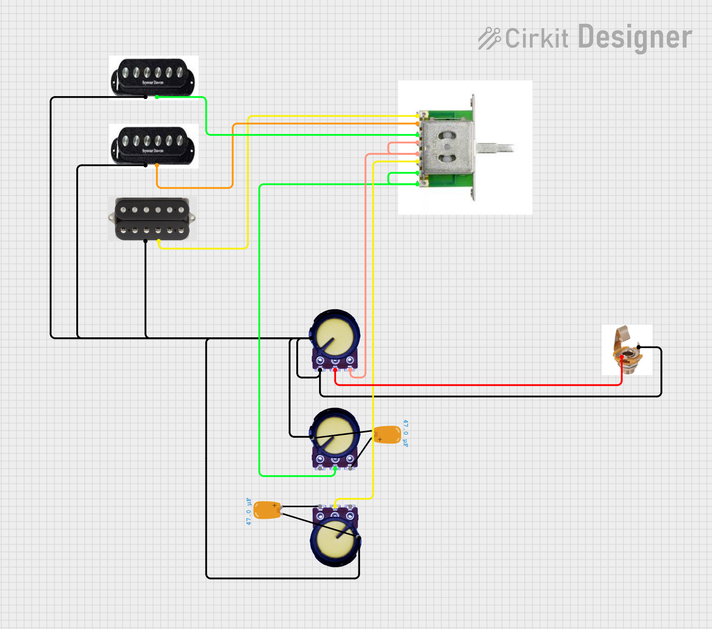 Open Project in Cirkit Designer
Explore Projects Built with Amphenol ACJS-MHDR 6.35mm Switched Stereo Jack
Open Project in Cirkit DesignerOpen Project in Cirkit DesignerOpen Project in Cirkit DesignerOpen Project in Cirkit DesignerCommon Applications
- Audio equipment such as mixers, amplifiers, and audio interfaces
- Musical instruments like electric guitars and keyboards
- Headphone jacks in professional audio systems
- Signal routing in audio processing circuits
Technical Specifications
Key Technical Details
| Parameter | Value |
|---|---|
| Manufacturer | Amphenol |
| Part Number | ACJS-MHDR |
| Connector Type | 6.35mm (1/4 inch) Stereo Jack |
| Switching Function | Normally closed (NC) switch |
| Contact Material | Nickel-plated |
| Housing Material | Thermoplastic |
| Mounting Style | Panel mount |
| Number of Contacts | 5 (Left, Right, Ground, Switch 1, Switch 2) |
| Operating Temperature | -20°C to +70°C |
Pin Configuration and Descriptions
The ACJS-MHDR has five pins, as detailed in the table below:
| Pin Number | Name | Description |
|---|---|---|
| 1 | Left (L) | Carries the left audio channel signal. |
| 2 | Right (R) | Carries the right audio channel signal. |
| 3 | Ground (G) | Common ground for the audio signals. |
| 4 | Switch 1 | Normally closed switch contact, opens when a plug is inserted. |
| 5 | Switch 2 | Normally closed switch contact, opens when a plug is inserted. |
Usage Instructions
How to Use the Component in a Circuit
- Mounting the Jack: Secure the ACJS-MHDR to a panel or enclosure using the provided mounting hardware. Ensure the jack is properly aligned for easy plug insertion.
- Wiring the Audio Signals:
- Connect the
Left (L)pin to the left audio signal source. - Connect the
Right (R)pin to the right audio signal source. - Connect the
Ground (G)pin to the common ground of the circuit.
- Connect the
- Using the Switch Contacts:
- The
Switch 1andSwitch 2pins can be used to control other circuit elements. For example, they can disconnect a speaker when a headphone plug is inserted. - When no plug is inserted, the switch contacts are closed, allowing current to flow. When a plug is inserted, the contacts open, interrupting the circuit.
- The
Important Considerations and Best Practices
- Signal Integrity: Use shielded cables for audio signals to minimize noise and interference.
- Switch Ratings: Ensure the switch contacts are not subjected to currents or voltages beyond their rated capacity.
- Mechanical Stress: Avoid excessive force when inserting or removing plugs to prevent damage to the jack.
- Soldering: Use a soldering iron with a temperature-controlled tip to avoid overheating the pins during assembly.
Example: Connecting to an Arduino UNO
The ACJS-MHDR can be used with an Arduino UNO to detect when a plug is inserted. Below is an example circuit and code:
Circuit Description
- Connect
Switch 1to an Arduino digital input pin (e.g., pin 2). - Connect
Switch 2to the Arduino ground (GND). - Use a pull-up resistor (internal or external) to ensure a stable signal.
Arduino Code
// Define the pin connected to Switch 1
const int switchPin = 2;

// Variable to store the switch state
int switchState = 0;

void setup() {
  // Configure the switch pin as an input with an internal pull-up resistor
  pinMode(switchPin, INPUT_PULLUP);

  // Initialize serial communication for debugging
  Serial.begin(9600);
}

void loop() {
  // Read the state of the switch (LOW when plug is inserted)
  switchState = digitalRead(switchPin);

  // Print the switch state to the serial monitor
  if (switchState == LOW) {
    Serial.println("Plug inserted");
  } else {
    Serial.println("No plug detected");
  }

  // Add a small delay to avoid spamming the serial monitor
  delay(500);
}
Troubleshooting and FAQs
Common Issues
- No Audio Signal:
- Check the connections to the
Left (L),Right (R), andGround (G)pins. - Ensure the audio source and destination are powered and functioning correctly.
- Check the connections to the
- Switch Not Working:
- Verify the wiring of
Switch 1andSwitch 2. - Check for continuity using a multimeter to ensure the switch contacts are functioning.
- Verify the wiring of
- Noise or Interference:
- Use shielded cables and ensure proper grounding.
- Avoid running audio cables near high-power or high-frequency circuits.
Solutions and Tips
- Testing the Jack: Use a multimeter to test continuity between the pins and verify the switch operation.
- Plug Compatibility: Ensure the plug used is a standard 6.35mm stereo plug for proper contact alignment.
- Durability: Periodically inspect the jack for wear and tear, especially in high-use environments.
By following this documentation, users can effectively integrate the Amphenol ACJS-MHDR 6.35mm Switched Stereo Jack into their audio projects and troubleshoot common issues with ease.