Cirkit Designer
Your all-in-one circuit design IDE
Home /
Component Documentation
How to Use CAN-Board: Examples, Pinouts, and Specs
Introduction
The CAN-Board is a versatile circuit board designed to interface with the Controller Area Network (CAN) bus. This robust communication protocol is widely used in automotive and industrial applications to enable reliable data exchange between microcontrollers and devices without the need for a host computer. The CAN-Board facilitates seamless integration into various systems, making it an essential component for modern electronic designs.
Explore Projects Built with CAN-Board
Dual Raspberry Pi 2B CAN BUS Communication Interface with Pushbutton Interaction
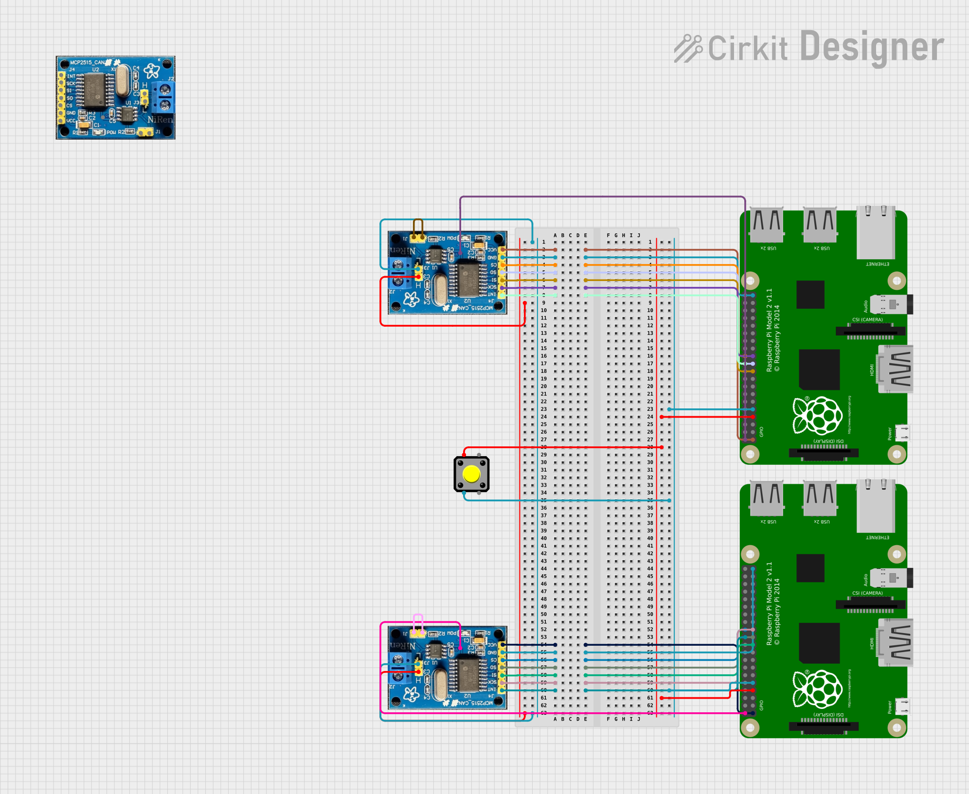
This circuit features two Raspberry Pi 2B microcontrollers connected to separate CAN BUS modules, forming a CAN network for data exchange. A pushbutton is included for user interaction, interfaced with GPIO pins on both Raspberry Pis.
Raspberry Pi Pico W CAN Bus Interface with USB-CAN Adapter
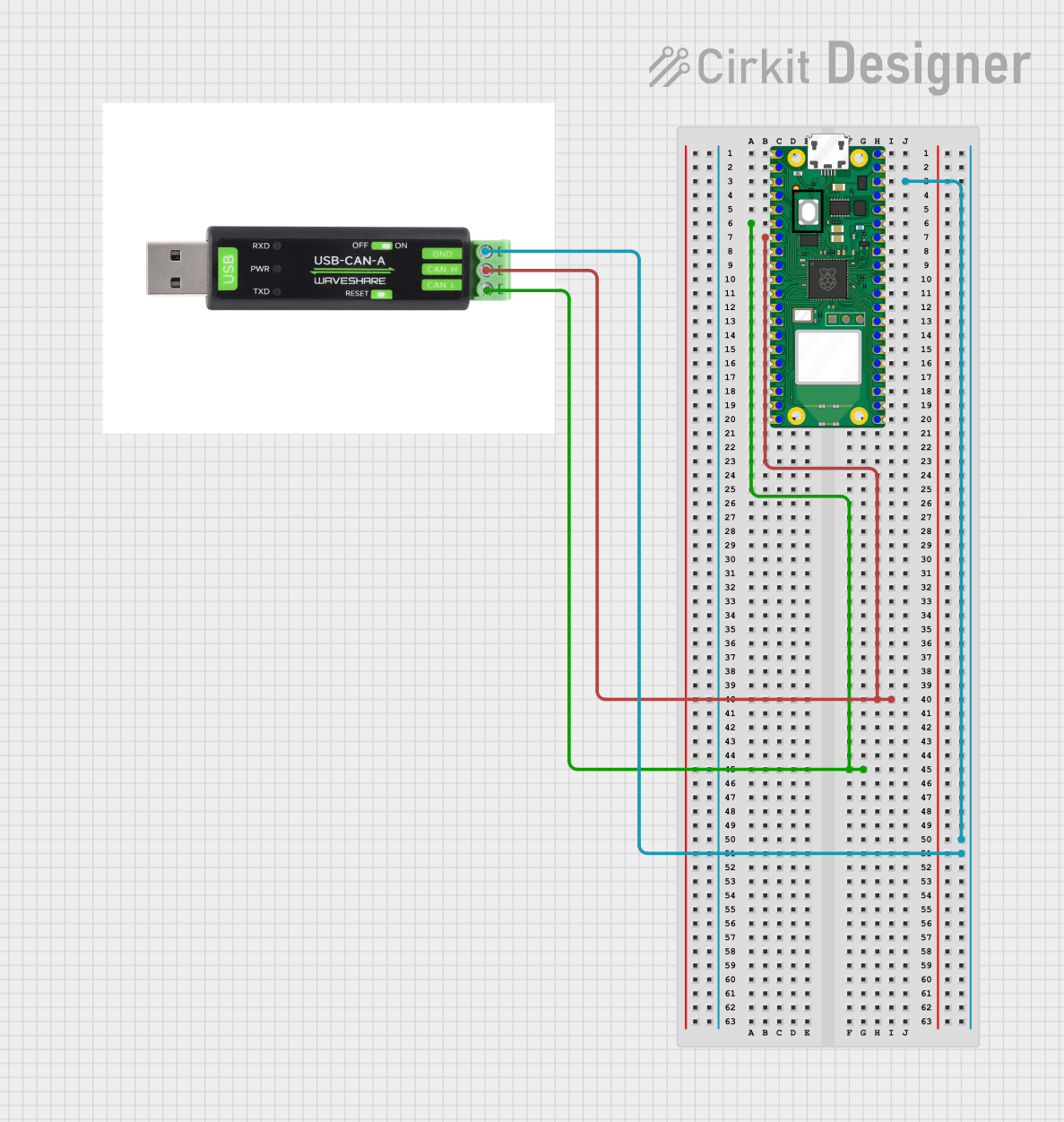
This circuit connects a Raspberry Pi Pico W microcontroller to a USB-CAN adapter, enabling the microcontroller to interface with a CAN bus. The connections include grounding the USB-CAN adapter and linking the CAN_H and CAN_L lines to the appropriate pins on the Raspberry Pi Pico W.
Arduino and MCP2515 CAN Bus Communication with LED Indicators
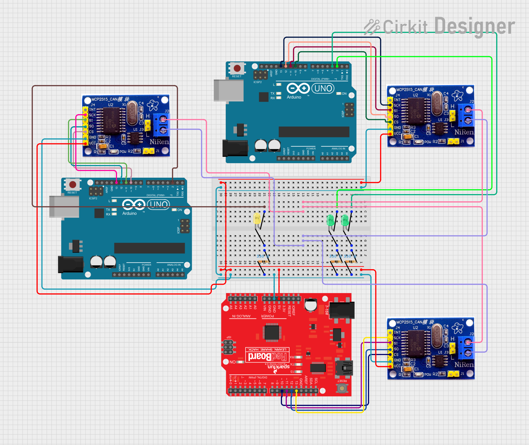
This circuit consists of two Arduino UNOs and a SparkFun RedBoard, each interfaced with MCP2515 CAN controllers for communication. Additionally, the circuit includes multiple LEDs with current-limiting resistors, which are controlled by the microcontrollers to indicate various states or activities.
ESP32-S3 GPS Logger and Wind Speed Display with Dual OLED and CAN Bus
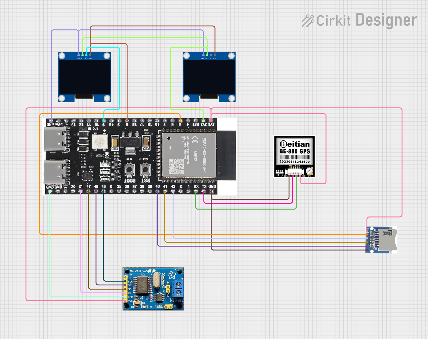
This circuit features an ESP32-S3 microcontroller interfaced with an SD card, two OLED displays, a GPS module, and a CAN bus module. It records GPS data to the SD card every second, displays speed in knots on one OLED display, and shows wind speed from the CAN bus in NMEA 2000 format on the other OLED display.
Explore Projects Built with CAN-Board
Dual Raspberry Pi 2B CAN BUS Communication Interface with Pushbutton Interaction
This circuit features two Raspberry Pi 2B microcontrollers connected to separate CAN BUS modules, forming a CAN network for data exchange. A pushbutton is included for user interaction, interfaced with GPIO pins on both Raspberry Pis.
Raspberry Pi Pico W CAN Bus Interface with USB-CAN Adapter
This circuit connects a Raspberry Pi Pico W microcontroller to a USB-CAN adapter, enabling the microcontroller to interface with a CAN bus. The connections include grounding the USB-CAN adapter and linking the CAN_H and CAN_L lines to the appropriate pins on the Raspberry Pi Pico W.
Arduino and MCP2515 CAN Bus Communication with LED Indicators
This circuit consists of two Arduino UNOs and a SparkFun RedBoard, each interfaced with MCP2515 CAN controllers for communication. Additionally, the circuit includes multiple LEDs with current-limiting resistors, which are controlled by the microcontrollers to indicate various states or activities.
ESP32-S3 GPS Logger and Wind Speed Display with Dual OLED and CAN Bus
This circuit features an ESP32-S3 microcontroller interfaced with an SD card, two OLED displays, a GPS module, and a CAN bus module. It records GPS data to the SD card every second, displays speed in knots on one OLED display, and shows wind speed from the CAN bus in NMEA 2000 format on the other OLED display.
Common Applications and Use Cases
- Automotive Systems: Engine control units, transmission control, and in-vehicle networking.
- Industrial Automation: Factory automation, process control, and industrial machinery.
- Robotics: Communication between sensors, actuators, and control units.
- IoT Devices: Smart home systems, environmental monitoring, and remote sensing.
Technical Specifications
Key Technical Details
| Parameter | Value |
|---|---|
| Operating Voltage | 5V |
| Communication | CAN 2.0B, up to 1 Mbps |
| Interface | SPI |
| Power Consumption | Typically 70 mA |
| Temperature Range | -40°C to +85°C |
Pin Configuration and Descriptions
| Pin Number | Pin Name | Description |
|---|---|---|
| 1 | VCC | Power supply (5V) |
| 2 | GND | Ground |
| 3 | CS | Chip Select (SPI) |
| 4 | SCK | Serial Clock (SPI) |
| 5 | SI | Serial Data In (SPI) |
| 6 | SO | Serial Data Out (SPI) |
| 7 | INT | Interrupt Output |
| 8 | CANH | CAN High (connects to CAN bus) |
| 9 | CANL | CAN Low (connects to CAN bus) |
Usage Instructions
How to Use the CAN-Board in a Circuit
- Power Supply: Connect the VCC pin to a 5V power source and the GND pin to the ground.
- SPI Interface: Connect the CS, SCK, SI, and SO pins to the corresponding SPI pins on your microcontroller.
- CAN Bus Connection: Connect the CANH and CANL pins to the CAN bus lines.
- Interrupt Handling: Connect the INT pin to an interrupt-capable pin on your microcontroller if needed.
Important Considerations and Best Practices
- Termination Resistors: Ensure that the CAN bus is properly terminated with 120-ohm resistors at both ends to prevent signal reflections.
- Power Supply Stability: Use a stable 5V power supply to avoid communication errors.
- Shielding and Grounding: In noisy environments, use shielded cables and proper grounding techniques to minimize interference.
- Software Configuration: Configure the CAN controller settings (e.g., baud rate) to match the requirements of your CAN network.
Example Code for Arduino UNO
#include <SPI.h>
#include <mcp_can.h>

// Define the CS pin for the CAN-Board
const int CS_PIN = 10;

// Create an instance of the MCP_CAN class
MCP_CAN CAN(CS_PIN);

void setup() {
  Serial.begin(115200);

  // Initialize the CAN bus at 500 kbps
  if (CAN.begin(CAN_500KBPS) == CAN_OK) {
    Serial.println("CAN bus initialized successfully");
  } else {
    Serial.println("CAN bus initialization failed");
    while (1);
  }
}

void loop() {
  // Example: Send a CAN message
  byte data[8] = {0x00, 0x01, 0x02, 0x03, 0x04, 0x05, 0x06, 0x07};
  if (CAN.sendMsgBuf(0x100, 0, 8, data) == CAN_OK) {
    Serial.println("Message sent successfully");
  } else {
    Serial.println("Message sending failed");
  }

  delay(1000); // Wait for 1 second before sending the next message
}
Troubleshooting and FAQs
Common Issues Users Might Face
CAN Bus Initialization Failure:
- Solution: Check the power supply and connections. Ensure the CAN bus is properly terminated.
Message Sending Failure:
- Solution: Verify the CAN bus speed and configuration. Check for bus errors and collisions.
No Communication on CAN Bus:
- Solution: Ensure all devices on the CAN bus are powered and correctly configured. Check for loose or broken connections.
Solutions and Tips for Troubleshooting
- Check Connections: Ensure all connections are secure and correctly wired.
- Verify Power Supply: Use a stable and sufficient power supply for the CAN-Board and connected devices.
- Use Diagnostic Tools: Utilize CAN bus analyzers or oscilloscopes to diagnose communication issues.
- Consult Documentation: Refer to the microcontroller and CAN controller datasheets for detailed configuration and troubleshooting information.
By following this documentation, users can effectively integrate and utilize the CAN-Board in their projects, ensuring reliable and robust communication in various applications.