
How to Use Voltage Regulator: Examples, Pinouts, and Specs
 Design with Voltage Regulator in Cirkit Designer
Introduction
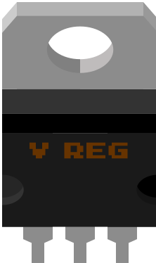
The LM317 is a versatile, adjustable voltage regulator manufactured by Texas Instruments. It is designed to provide a stable and constant output voltage, even when the input voltage or load conditions vary. This makes it an essential component in power supply circuits, ensuring reliable operation of electronic devices.
Common applications of the LM317 include:
- Power supplies for electronic circuits
- Battery chargers
- Adjustable voltage regulators
- Current regulators
- LED drivers
Explore Projects Built with Voltage Regulator
 Open Project in Cirkit Designer
 Open Project in Cirkit Designer
 Open Project in Cirkit Designer
 Open Project in Cirkit Designer
Explore Projects Built with Voltage Regulator
Open Project in Cirkit DesignerOpen Project in Cirkit DesignerOpen Project in Cirkit DesignerOpen Project in Cirkit DesignerTechnical Specifications
The LM317 is a three-terminal adjustable voltage regulator with the following key specifications:
| Parameter | Value |
|---|---|
| Input Voltage Range | 3 V to 40 V |
| Output Voltage Range | 1.25 V to 37 V |
| Maximum Output Current | 1.5 A |
| Line Regulation | 0.01% / V (typical) |
| Load Regulation | 0.1% (typical) |
| Thermal Shutdown Protection | Yes |
| Short-Circuit Protection | Yes |
| Package Types | TO-220, TO-92, SOT-223 |
Pin Configuration and Descriptions
The LM317 has three pins, as described in the table below:
| Pin Number | Pin Name | Description |
|---|---|---|
| 1 | Adjust | Used to set the output voltage via an external resistor divider network |
| 2 | Output | Regulated output voltage |
| 3 | Input | Unregulated input voltage (must be higher than the desired output voltage) |
Usage Instructions
How to Use the LM317 in a Circuit
To use the LM317 as an adjustable voltage regulator, follow these steps:
- Connect the Input pin to the unregulated DC voltage source.
- Use a resistor divider network (two resistors) between the Adjust pin and the Output pin to set the desired output voltage. The output voltage is determined by the formula:
[
V_{OUT} = V_{REF} \times \left(1 + \frac{R_2}{R_1}\right) + I_{ADJ} \times R_2
]
- (V_{REF}) is typically 1.25 V.
- (I_{ADJ}) is the adjustment pin current (typically 50 µA, negligible in most cases).
- Connect the Output pin to the load.
Example Circuit
Below is a basic circuit diagram for using the LM317 to provide an adjustable output voltage:
Input Voltage (Vin) ----+---- [LM317 Input Pin]
                        |
                        +---- [Resistor R1] ----+
                        |                       |
                        +---- [Adjust Pin]      |
                        |                       |
                        +---- [Resistor R2] ----+
                        |
Output Voltage (Vout) ---+---- [LM317 Output Pin]
Important Considerations and Best Practices
- Ensure the input voltage is at least 3 V higher than the desired output voltage to maintain proper regulation.
- Use a heat sink if the LM317 is expected to dissipate significant power.
- Add input and output capacitors (e.g., 0.1 µF and 1 µF, respectively) to improve stability and reduce noise.
- Avoid exceeding the maximum input voltage (40 V) or output current (1.5 A).
Arduino UNO Example
The LM317 can be used to power an Arduino UNO with a custom voltage. Below is an example code snippet to read the regulated voltage using the Arduino's analog input:
// Define the analog pin connected to the output of the LM317
const int voltagePin = A0;

void setup() {
  Serial.begin(9600); // Initialize serial communication
}

void loop() {
  int sensorValue = analogRead(voltagePin); // Read the analog value
  float voltage = sensorValue * (5.0 / 1023.0); // Convert to voltage
  Serial.print("Regulated Voltage: ");
  Serial.print(voltage);
  Serial.println(" V");
  delay(1000); // Wait for 1 second before the next reading
}
Note: Ensure the LM317's output voltage is within the Arduino's operating voltage range (5 V or 3.3 V).
Troubleshooting and FAQs
Common Issues and Solutions
Output Voltage is Incorrect
- Verify the resistor values in the voltage divider network.
- Ensure the input voltage is at least 3 V higher than the desired output voltage.
- Check for loose or incorrect connections.
LM317 Overheats
- Use a heat sink to dissipate excess heat.
- Ensure the load current does not exceed 1.5 A.
No Output Voltage
- Check if the input voltage is within the specified range.
- Verify that the capacitors are correctly connected and functional.
- Inspect for short circuits or damaged components.
FAQs
Q: Can the LM317 be used as a current regulator?
A: Yes, by connecting a resistor between the output and adjust pins, the LM317 can regulate current. The current is determined by (I = 1.25 / R), where (R) is the resistor value.
Q: What is the minimum load current for the LM317?
A: The LM317 requires a minimum load current of 10 mA to maintain proper regulation.
Q: Can I use the LM317 with AC input?
A: No, the LM317 requires a DC input. Use a rectifier and filter capacitor to convert AC to DC before connecting to the LM317.
Q: How do I calculate the power dissipation of the LM317?
A: Power dissipation is calculated as (P = (V_{IN} - V_{OUT}) \times I_{LOAD}). Ensure the power dissipation does not exceed the thermal limits of the package.
By following this documentation, you can effectively use the LM317 voltage regulator in your projects for stable and reliable voltage regulation.