Cirkit Designer LogoCirkit DesignerYour all-in-one circuit design IDE Launch Cirkit Designer App

How to Use POWER SUPPLY 12V 5AMP: Examples, Pinouts, and Specs

Image of POWER SUPPLY 12V 5AMPDesign with POWER SUPPLY 12V 5AMP in Cirkit Designer

Introduction

The POWER SUPPLY 12V 5AMP is an electronic device that converts electrical power from a source, typically alternating current (AC) from the mains, to a constant direct current (DC) voltage, delivering up to 5 amperes of current. This power supply is essential for powering a wide range of electronic devices and circuits that require a stable 12V DC power source.

Explore Projects Built with POWER SUPPLY 12V 5AMP

Use Cirkit Designer to design, explore, and prototype these projects online. Some projects support real-time simulation. Click "Open Project" to start designing instantly!
Image of Dual 5V Power Supply Distribution Circuit with Toggle Switch Control: A project utilizing POWER SUPPLY 12V 5AMP in a practical application

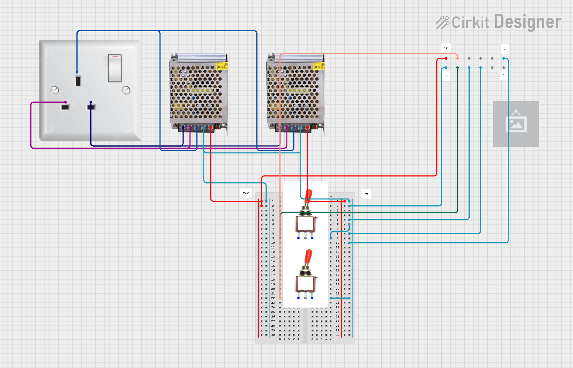
Dual 5V Power Supply Distribution Circuit with Toggle Switch Control

This circuit consists of two 5V 5A power supplies connected to an AC wall plug point, providing DC output through a 12-way connector. The ground connections from both power supplies are interconnected and also connected to the ground pins of two toggle switches. The DC outputs from the power supplies are separately connected to different pins on the 12-way connector, with each power supply output being switchable via one of the toggle switches.

Open Project in Cirkit Designer
Image of 12V Multi-Component Control Circuit: A project utilizing POWER SUPPLY 12V 5AMP in a practical application
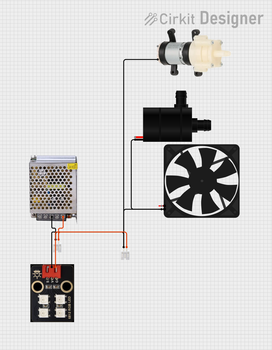
12V Multi-Component Control Circuit

This circuit appears to be a power distribution system that supplies power to various components from a 12V 5A power supply. It connects the negative terminal of the power supply to the ground (GND) pins of a mini diaphragm water pump, an RGB LED, a fan, and a water pump, while the positive DC output is connected to the positive pins of the RGB LED and presumably to other components through JST PH 2.0 connectors. The circuit lacks a controlling element, such as a microcontroller, suggesting that the components operate continuously or are switched externally.

Open Project in Cirkit Designer

Common Applications and Use Cases

Technical Specifications

Key Technical Details

Pin Configuration and Descriptions

Pin No. Description Notes
1 AC Input (L) Live wire from AC mains
2 AC Input (N) Neutral wire from AC mains
3 Ground (⏚) Protective earth ground
4 DC Output (+12V) Positive output terminal
5 DC Output (COM/GND) Common or ground output terminal

Usage Instructions

How to Use the Component in a Circuit

  1. Connecting to AC Mains:

    • Ensure the power supply is disconnected from any power source.
    • Connect the live (L) and neutral (N) wires to the respective AC input pins.
    • Attach the ground wire to the ground pin for safety.
  2. Connecting to a Device:

    • Connect the positive terminal of the device to the +12V DC output pin.
    • Connect the negative terminal of the device to the COM/GND output pin.

Important Considerations and Best Practices

Troubleshooting and FAQs

Common Issues Users Might Face

Solutions and Tips for Troubleshooting

FAQs

For any further assistance or technical support, please refer to the manufacturer's customer service or technical support team.