
How to Use Adafruit HUZZAH ESP8266 Breakout: Examples, Pinouts, and Specs
 Design with Adafruit HUZZAH ESP8266 Breakout in Cirkit Designer
Introduction
The Adafruit HUZZAH ESP8266 Breakout (Manufacturer Part ID: 2471) is a compact Wi-Fi microcontroller board designed for Internet of Things (IoT) applications. Powered by the ESP8266 chip, this breakout board offers built-in Wi-Fi capabilities, making it ideal for wireless communication projects. It features multiple GPIO pins for interfacing with sensors, actuators, and other peripherals. Additionally, it is compatible with the Arduino IDE, enabling easy programming and integration into a wide range of projects.
Explore Projects Built with Adafruit HUZZAH ESP8266 Breakout
 Open Project in Cirkit Designer
 Open Project in Cirkit Designer
 Open Project in Cirkit Designer
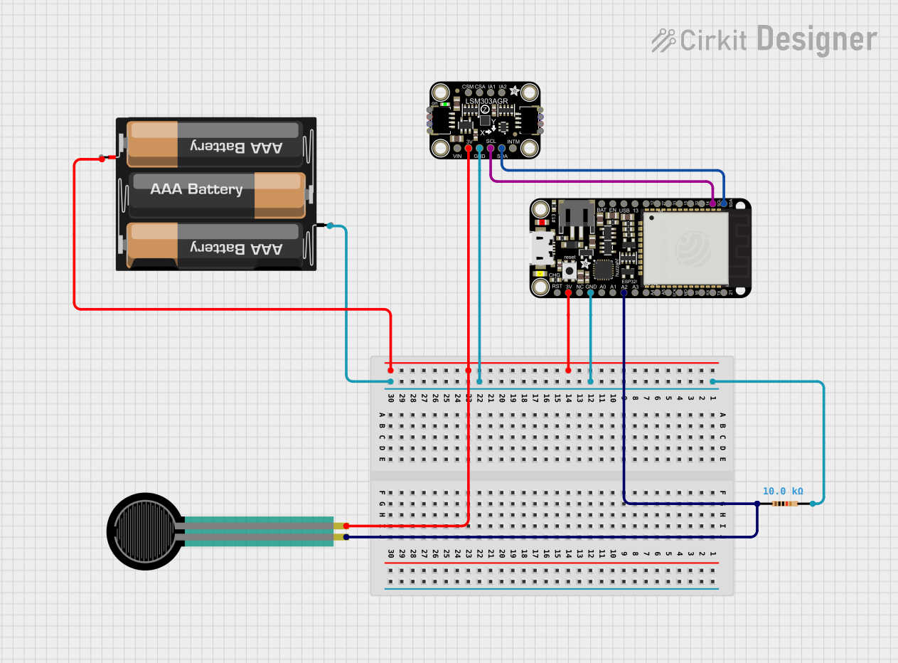 Open Project in Cirkit Designer
Explore Projects Built with Adafruit HUZZAH ESP8266 Breakout
Open Project in Cirkit DesignerOpen Project in Cirkit DesignerOpen Project in Cirkit DesignerOpen Project in Cirkit DesignerCommon Applications
- Home automation systems
- Wireless sensor networks
- IoT devices and prototypes
- Remote data logging
- Smart appliances and wearables
Technical Specifications
Key Technical Details
| Parameter | Value |
|---|---|
| Microcontroller | ESP8266 (Tensilica L106 32-bit processor) |
| Operating Voltage | 3.3V |
| Input Voltage (VIN) | 3.3V to 6V |
| Flash Memory | 4MB |
| GPIO Pins | 9 (including UART, SPI, I2C support) |
| Wi-Fi Standard | 802.11 b/g/n |
| Power Consumption | ~70mA (active), ~10µA (deep sleep) |
| Dimensions | 25mm x 43mm |
Pin Configuration and Descriptions
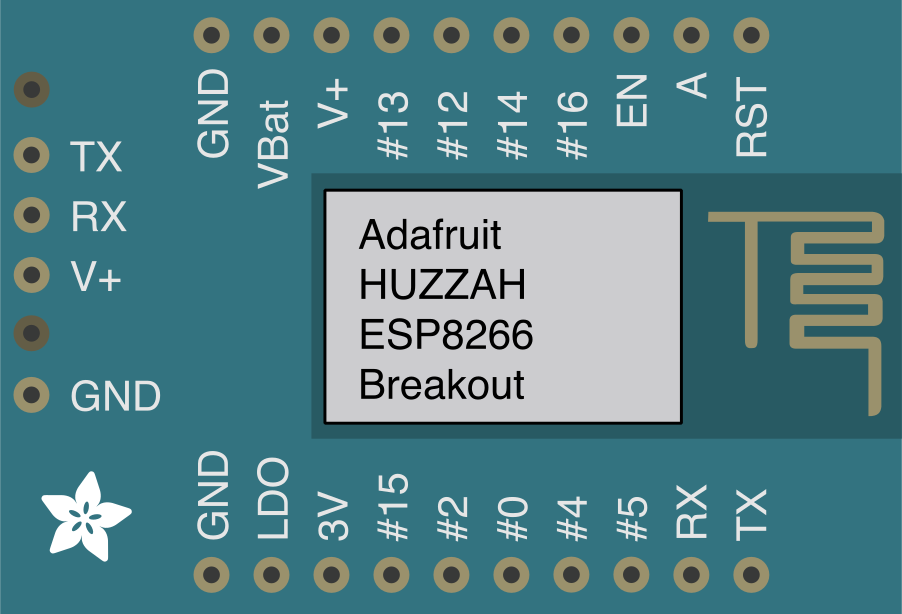
The Adafruit HUZZAH ESP8266 Breakout has 12 pins, including power, ground, and GPIO pins. Below is the pinout description:
| Pin Name | Function | Description |
|---|---|---|
| VIN | Power Input | Accepts 3.3V to 6V input voltage. |
| GND | Ground | Connect to the ground of the circuit. |
| 3V3 | 3.3V Output | Regulated 3.3V output from the onboard regulator. |
| EN | Enable | Pull high to enable the chip. |
| RST | Reset | Active low reset pin. |
| TX | UART Transmit | Serial data output for UART communication. |
| RX | UART Receive | Serial data input for UART communication. |
| GPIO0 | General Purpose I/O | Can also be used for boot mode selection. |
| GPIO2 | General Purpose I/O | Standard GPIO pin. |
| GPIO4 | General Purpose I/O | Standard GPIO pin. |
| GPIO5 | General Purpose I/O | Standard GPIO pin. |
| ADC | Analog Input | 10-bit ADC input (0-1V range). |
Usage Instructions
How to Use the Component in a Circuit
Powering the Board:
- Connect the VIN pin to a power source (3.3V to 6V). Alternatively, you can power the board via the 3V3 pin with a regulated 3.3V supply.
- Connect the GND pin to the ground of your circuit.
Programming the Board:
- Install the ESP8266 board package in the Arduino IDE.
- Connect the board to your computer using a USB-to-serial adapter (e.g., FTDI or CP2102).
- Ensure the GPIO0 pin is pulled LOW during programming to enter bootloader mode.
Connecting Peripherals:
- Use the GPIO pins to interface with sensors, actuators, or other devices.
- The ADC pin can be used to read analog signals (ensure the input voltage is within the 0-1V range).
Wi-Fi Configuration:
- Use the ESP8266WiFi library in the Arduino IDE to configure and connect to a Wi-Fi network.
Important Considerations and Best Practices
- Voltage Levels: The GPIO pins operate at 3.3V logic levels. Avoid applying 5V to any pin to prevent damage.
- Power Supply: Ensure a stable power supply to avoid unexpected resets or instability.
- Deep Sleep Mode: Use deep sleep mode to conserve power in battery-powered applications.
- Boot Mode Selection: GPIO0 and GPIO2 must be configured correctly for normal operation or programming mode.
Example Code for Arduino IDE
Below is an example code to connect the HUZZAH ESP8266 to a Wi-Fi network and print the IP address:
#include <ESP8266WiFi.h> // Include the ESP8266 Wi-Fi library

// Replace with your network credentials
const char* ssid = "Your_SSID";       // Your Wi-Fi SSID
const char* password = "Your_Password"; // Your Wi-Fi password

void setup() {
  Serial.begin(115200); // Initialize serial communication at 115200 baud
  delay(10);

  Serial.println();
  Serial.println("Connecting to Wi-Fi...");

  // Connect to Wi-Fi
  WiFi.begin(ssid, password);

  // Wait until the connection is established
  while (WiFi.status() != WL_CONNECTED) {
    delay(500);
    Serial.print(".");
  }

  Serial.println();
  Serial.println("Wi-Fi connected!");
  Serial.print("IP Address: ");
  Serial.println(WiFi.localIP()); // Print the assigned IP address
}

void loop() {
  // Add your main code here
}
Troubleshooting and FAQs
Common Issues and Solutions
The board does not respond or program correctly:
- Ensure GPIO0 is pulled LOW during programming.
- Check the USB-to-serial adapter connections (TX to RX, RX to TX).
- Verify that the correct COM port and board type are selected in the Arduino IDE.
Wi-Fi connection fails:
- Double-check the SSID and password in your code.
- Ensure the Wi-Fi network is within range and operational.
- Restart the board and router if necessary.
The board resets unexpectedly:
- Verify that the power supply is stable and capable of providing sufficient current.
- Avoid using long or thin wires for power connections.
ADC readings are incorrect:
- Ensure the input voltage to the ADC pin is within the 0-1V range.
- Use a voltage divider if necessary to scale down higher voltages.
FAQs
Q: Can I power the board using a USB cable?
A: No, the HUZZAH ESP8266 Breakout does not have a built-in USB port. You need a USB-to-serial adapter to program and power the board.
Q: What is the maximum current draw of the board?
A: The board typically draws ~70mA during operation but can spike up to 250mA during Wi-Fi transmissions.
Q: Can I use 5V logic devices with this board?
A: No, the GPIO pins operate at 3.3V logic levels. Use a level shifter if interfacing with 5V devices.
Q: How do I reset the board?
A: Pull the RST pin LOW momentarily to reset the board.
This concludes the documentation for the Adafruit HUZZAH ESP8266 Breakout.