
How to Use DIODE-SCHOTTKY: Examples, Pinouts, and Specs
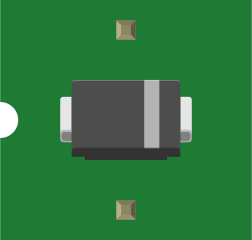
 Design with DIODE-SCHOTTKY in Cirkit Designer
Introduction
A Schottky diode is a semiconductor device that allows current to flow in one direction with a low forward voltage drop and fast switching speeds. Unlike standard diodes, Schottky diodes use a metal-semiconductor junction instead of a p-n junction, which gives them their unique characteristics. These diodes are widely used in applications requiring high efficiency and fast switching.
Explore Projects Built with DIODE-SCHOTTKY
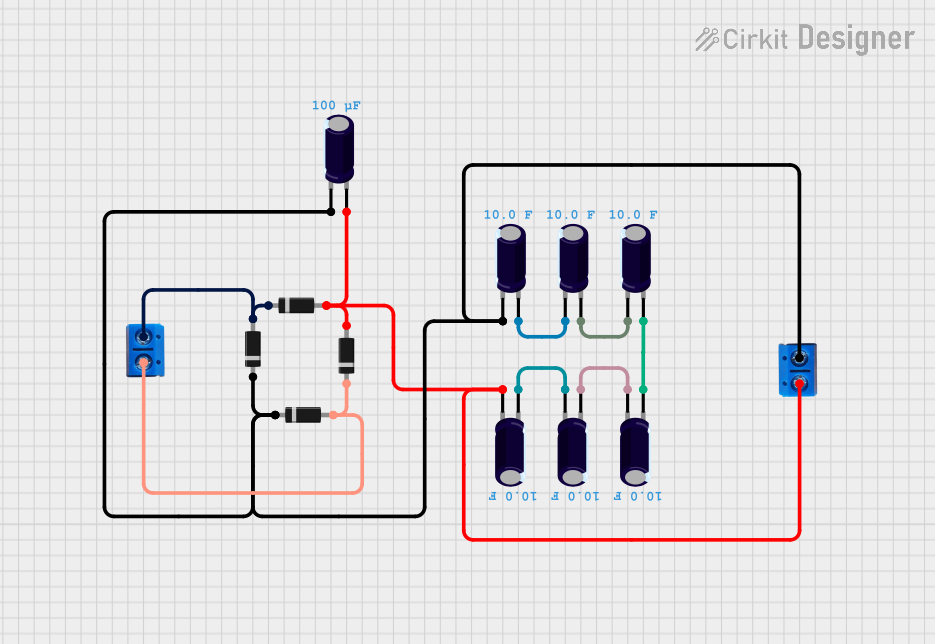 Open Project in Cirkit Designer
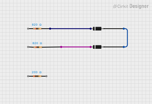 Open Project in Cirkit Designer
 Open Project in Cirkit Designer
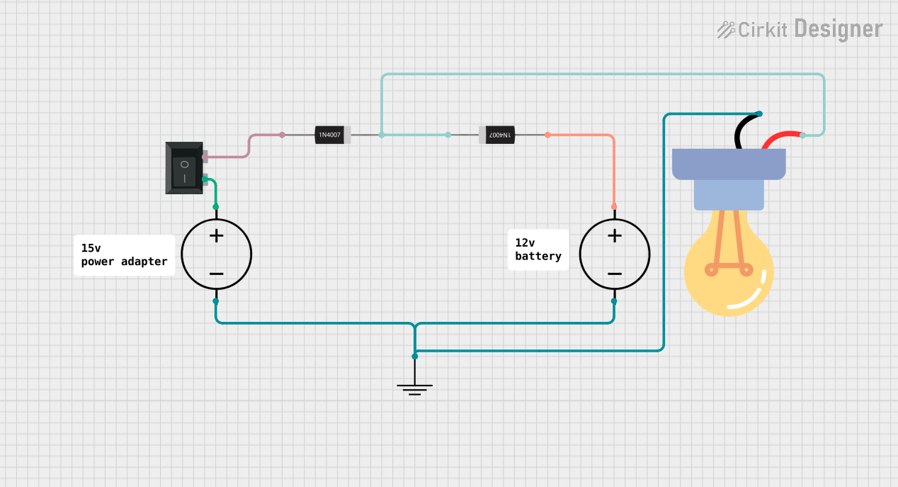 Open Project in Cirkit Designer
Explore Projects Built with DIODE-SCHOTTKY
Open Project in Cirkit DesignerOpen Project in Cirkit DesignerOpen Project in Cirkit DesignerOpen Project in Cirkit DesignerCommon Applications and Use Cases
- Power rectification in power supplies
- High-frequency switching circuits
- Voltage clamping and protection circuits
- RF (radio frequency) applications
- Solar panel bypass diodes
- Low-voltage, high-efficiency DC-DC converters
Technical Specifications
Below are the general technical specifications for a typical Schottky diode. Note that specific values may vary depending on the model and manufacturer.
Key Technical Details
- Forward Voltage Drop (Vf): Typically 0.2V to 0.45V
- Reverse Leakage Current (Ir): Typically in the range of microamps (µA) to milliamps (mA)
- Maximum Reverse Voltage (Vr): Commonly ranges from 20V to 200V
- Maximum Forward Current (If): Typically ranges from 1A to 40A
- Switching Speed: Nanoseconds (ns) range
- Junction Temperature (Tj): -55°C to +150°C (varies by model)
Pin Configuration and Descriptions
Schottky diodes are typically packaged in two-terminal configurations. Below is a table describing the pins:
| Pin Number | Name | Description |
|---|---|---|
| 1 | Anode | Positive terminal; current enters here. |
| 2 | Cathode | Negative terminal; current exits here. |
For surface-mount packages (e.g., SOD-123, SOT-23) or through-hole packages (e.g., DO-41), the pin layout may vary slightly, but the anode and cathode are always clearly marked.
Usage Instructions
How to Use the Component in a Circuit
- Identify the Anode and Cathode: The cathode is typically marked with a stripe on the diode body.
- Connect in the Correct Orientation: Ensure the anode is connected to the positive side of the circuit and the cathode to the negative side.
- Choose the Right Diode for Your Application:
- Verify the maximum reverse voltage (Vr) and forward current (If) ratings meet your circuit requirements.
- Select a diode with a low forward voltage drop for efficiency.
- Add a Series Resistor if Necessary: In some cases, a resistor may be needed to limit current through the diode.
Important Considerations and Best Practices
- Thermal Management: Schottky diodes can generate heat under high current. Use heat sinks or proper PCB design to dissipate heat.
- Reverse Voltage Protection: Ensure the reverse voltage rating of the diode is not exceeded to prevent damage.
- Parasitic Capacitance: In high-frequency circuits, consider the diode's capacitance, as it may affect performance.
- Avoid Overcurrent: Exceeding the maximum forward current can damage the diode.
Example: Using a Schottky Diode with an Arduino UNO
Schottky diodes are often used in circuits with microcontrollers like the Arduino UNO for voltage protection or rectification. Below is an example of using a Schottky diode for reverse polarity protection:
Circuit Description
- The Schottky diode is placed in series with the Arduino's power input to prevent damage if the power supply is connected in reverse.
Code Example
// Example: Basic Arduino sketch to blink an LED
// This assumes a Schottky diode is used for reverse polarity protection
// on the Arduino's power input.

const int ledPin = 13; // Pin connected to the onboard LED

void setup() {
  pinMode(ledPin, OUTPUT); // Set the LED pin as an output
}

void loop() {
  digitalWrite(ledPin, HIGH); // Turn the LED on
  delay(1000);               // Wait for 1 second
  digitalWrite(ledPin, LOW);  // Turn the LED off
  delay(1000);               // Wait for 1 second
}
Troubleshooting and FAQs
Common Issues Users Might Face
Diode Overheating:
- Cause: Exceeding the maximum forward current or insufficient heat dissipation.
- Solution: Use a diode with a higher current rating or improve thermal management.
High Reverse Leakage Current:
- Cause: Operating the diode near its maximum reverse voltage or at high temperatures.
- Solution: Choose a diode with a lower reverse leakage current specification.
Circuit Not Working as Expected:
- Cause: Incorrect orientation of the diode.
- Solution: Verify the anode and cathode connections.
Voltage Drop Too High:
- Cause: Using a standard diode instead of a Schottky diode.
- Solution: Ensure you are using a Schottky diode with a low forward voltage drop.
Solutions and Tips for Troubleshooting
- Check the Diode's Orientation: Use a multimeter in diode mode to verify the anode and cathode.
- Measure Voltage Drops: Use a multimeter to measure the forward voltage drop and ensure it matches the expected value.
- Inspect for Damage: Look for physical damage or discoloration on the diode, which may indicate overheating or failure.
- Verify Circuit Design: Double-check the circuit schematic and ensure the diode's ratings match the application requirements.
By following these guidelines, you can effectively use a Schottky diode in your electronic projects and troubleshoot common issues.