How to Use IMU 9DOF(lcm20600+AK09918): Examples, Pinouts, and Specs
Introduction
The Grove IMU 9DOF is a high-performance Inertial Measurement Unit (IMU) that integrates a 9-axis sensor system. It combines the LCM20600, a 6-axis motion sensor (3-axis gyroscope and 3-axis accelerometer), with the AK09918, a 3-axis magnetometer. This combination enables precise motion tracking and orientation detection, making it ideal for applications such as robotics, drones, wearable devices, and gaming controllers.
Explore Projects Built with IMU 9DOF(lcm20600+AK09918)


Explore Projects Built with IMU 9DOF(lcm20600+AK09918)
Common Applications
- Motion tracking in robotics and drones
- Orientation detection in wearable devices
- Gesture recognition in gaming controllers
- Navigation systems for autonomous vehicles
- Virtual reality (VR) and augmented reality (AR) systems
Technical Specifications
Key Technical Details
| Parameter | Value |
|---|---|
| Gyroscope Range | ±250, ±500, ±1000, ±2000 dps |
| Accelerometer Range | ±2g, ±4g, ±8g, ±16g |
| Magnetometer Range | ±1200 µT |
| Communication Interface | I2C |
| Operating Voltage | 3.3V / 5V |
| Operating Temperature | -40°C to +85°C |
| Dimensions | 20mm x 40mm |
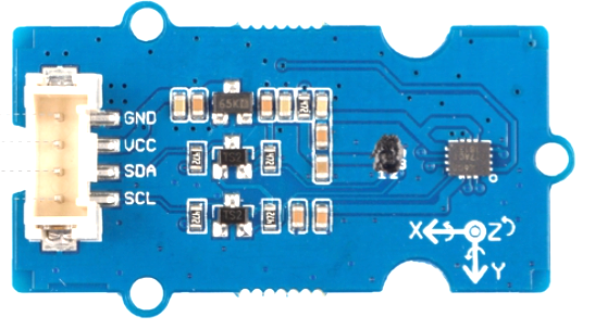
Pin Configuration
The Grove IMU 9DOF uses a standard Grove I2C interface. Below is the pin configuration:
| Pin Name | Description |
|---|---|
| VCC | Power supply (3.3V or 5V) |
| GND | Ground |
| SDA | I2C data line |
| SCL | I2C clock line |
Usage Instructions
How to Use the Component in a Circuit
Connect the IMU to a Microcontroller:
- Use a Grove cable to connect the IMU 9DOF to an I2C port on your microcontroller (e.g., Arduino UNO).
- Ensure the VCC pin is connected to a 3.3V or 5V power source, and the GND pin is connected to ground.
Install Required Libraries:
- For Arduino, install the
Adafruit_Sensorlibrary and theSeeed_9DOF_IMUlibrary from the Arduino Library Manager.
- For Arduino, install the
Write and Upload Code:
- Use the example code below to initialize the IMU and read sensor data.
Example Code for Arduino UNO
#include <Wire.h>
#include "Seeed_9DOF_IMU.h" // Include the library for the Grove IMU 9DOF

// Create an instance of the IMU class
Seeed_9DOF_IMU imu;

void setup() {
  Serial.begin(9600); // Initialize serial communication at 9600 baud
  Wire.begin();       // Initialize I2C communication

  // Initialize the IMU
  if (!imu.begin()) {
    Serial.println("Failed to initialize IMU!");
    while (1); // Halt the program if initialization fails
  }
  Serial.println("IMU initialized successfully!");
}

void loop() {
  // Variables to store sensor data
  float ax, ay, az; // Accelerometer data
  float gx, gy, gz; // Gyroscope data
  float mx, my, mz; // Magnetometer data

  // Read accelerometer data
  imu.getAccel(&ax, &ay, &az);
  Serial.print("Accel: ");
  Serial.print(ax); Serial.print(", ");
  Serial.print(ay); Serial.print(", ");
  Serial.println(az);

  // Read gyroscope data
  imu.getGyro(&gx, &gy, &gz);
  Serial.print("Gyro: ");
  Serial.print(gx); Serial.print(", ");
  Serial.print(gy); Serial.print(", ");
  Serial.println(gz);

  // Read magnetometer data
  imu.getMag(&mx, &my, &mz);
  Serial.print("Mag: ");
  Serial.print(mx); Serial.print(", ");
  Serial.print(my); Serial.print(", ");
  Serial.println(mz);

  delay(500); // Wait for 500ms before the next reading
}
Important Considerations and Best Practices
- Power Supply: Ensure the IMU is powered with the correct voltage (3.3V or 5V) to avoid damage.
- I2C Address: The default I2C address for the IMU is
0x68for the LCM20600 and0x0Cfor the AK09918. Ensure no address conflicts with other devices on the I2C bus. - Calibration: Perform sensor calibration for accurate readings, especially for the magnetometer.
- Mounting Orientation: Mount the IMU securely and in the correct orientation to ensure accurate motion tracking.
Troubleshooting and FAQs
Common Issues and Solutions
IMU Not Detected:
- Cause: Incorrect wiring or I2C address conflict.
- Solution: Double-check the connections and ensure the correct I2C address is used in the code.
Inaccurate Sensor Readings:
- Cause: Lack of calibration or external magnetic interference.
- Solution: Perform sensor calibration and avoid placing the IMU near magnetic or metallic objects.
No Data Output:
- Cause: Incorrect library installation or initialization failure.
- Solution: Verify that the required libraries are installed and the IMU is initialized correctly in the code.
FAQs
Q: Can the IMU 9DOF be used with a Raspberry Pi?
A: Yes, the IMU 9DOF can be used with a Raspberry Pi via the I2C interface. Use Python libraries such as smbus to communicate with the IMU.
Q: How do I calibrate the magnetometer?
A: Rotate the IMU in all directions to collect data for calibration. Use software tools or algorithms to compute the calibration offsets.
Q: What is the maximum sampling rate of the IMU?
A: The LCM20600 supports a maximum sampling rate of 1 kHz for the gyroscope and accelerometer. The AK09918 supports a maximum sampling rate of 100 Hz for the magnetometer.
By following this documentation, you can effectively integrate and utilize the Grove IMU 9DOF in your projects.