
How to Use 5V Relay: Examples, Pinouts, and Specs
 Design with 5V Relay in Cirkit Designer
Introduction
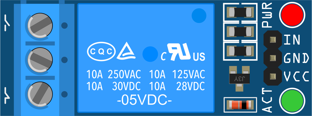
A 5V relay is an electromechanical switch that uses a low voltage (5V) control signal to open or close a circuit, allowing for the control of higher voltage devices. It typically consists of a coil, an armature, and contacts. This component is widely used in applications where electrical isolation and control of high-power devices are required.
Explore Projects Built with 5V Relay
 Open Project in Cirkit Designer
 Open Project in Cirkit Designer
 Open Project in Cirkit Designer
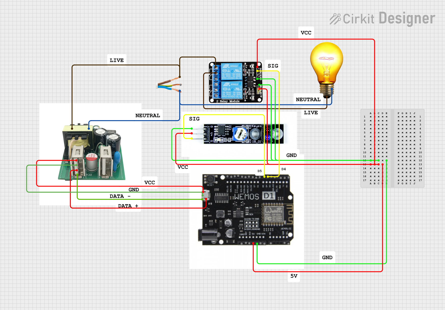 Open Project in Cirkit Designer
Explore Projects Built with 5V Relay
Open Project in Cirkit DesignerOpen Project in Cirkit DesignerOpen Project in Cirkit DesignerOpen Project in Cirkit DesignerCommon Applications and Use Cases
- Home automation systems (e.g., controlling lights, fans, or appliances)
- Industrial control systems
- Motor control circuits
- IoT projects for switching high-voltage devices
- Automotive electronics for controlling accessories
Technical Specifications
Below are the key technical details of a standard 5V relay:
| Parameter | Value |
|---|---|
| Operating Voltage | 5V DC |
| Trigger Voltage | 3.75V to 5V DC |
| Trigger Current | 15mA to 20mA |
| Contact Rating | 10A at 250V AC / 10A at 30V DC |
| Coil Resistance | ~70Ω |
| Switching Time | 5ms (operate), 5ms (release) |
| Electrical Isolation | Yes (via relay contacts) |
| Number of Contacts | Single Pole Double Throw (SPDT) |
| Dimensions | ~28mm x 10mm x 15mm |
Pin Configuration and Descriptions
The 5V relay typically has 5 pins, as described in the table below:
| Pin Name | Description |
|---|---|
| Coil+ | Positive terminal of the relay coil (connect to 5V control signal). |
| Coil- | Negative terminal of the relay coil (connect to ground). |
| Common (COM) | Common terminal for the relay switch. |
| Normally Open (NO) | Open circuit when the relay is inactive; closed when the relay is activated. |
| Normally Closed (NC) | Closed circuit when the relay is inactive; open when the relay is activated. |
Usage Instructions
How to Use the 5V Relay in a Circuit
- Power the Relay Coil: Connect the
Coil+pin to a 5V DC control signal and theCoil-pin to ground. This energizes the relay coil and activates the switch. - Connect the Load:
- For devices that should turn on when the relay is activated, connect the load between the
COMandNOpins. - For devices that should turn off when the relay is activated, connect the load between the
COMandNCpins.
- For devices that should turn on when the relay is activated, connect the load between the
- Protect the Circuit: Use a flyback diode across the relay coil to prevent voltage spikes when the relay is deactivated.
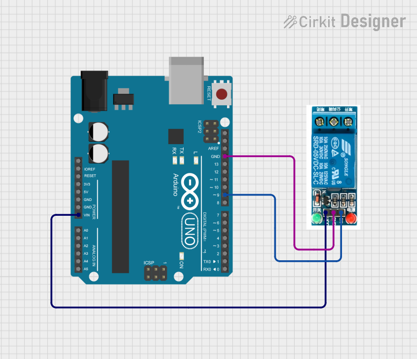
- Control with Microcontroller: If using a microcontroller (e.g., Arduino UNO), connect the control signal to a digital output pin and use a transistor to amplify the current if needed.
Important Considerations and Best Practices
- Isolation: Ensure proper electrical isolation between the control circuit and the high-voltage load.
- Flyback Diode: Always use a flyback diode (e.g., 1N4007) across the relay coil to protect the control circuit from voltage spikes.
- Current Requirements: Verify that the control circuit can supply the required current (15-20mA) to activate the relay. Use a transistor or relay driver module if necessary.
- Contact Ratings: Do not exceed the relay's contact ratings (10A at 250V AC or 30V DC) to avoid damage.
Example: Using a 5V Relay with Arduino UNO
Below is an example of how to control a 5V relay using an Arduino UNO:
// Example: Controlling a 5V relay with Arduino UNO
// Pin 7 is used to control the relay
const int relayPin = 7;

void setup() {
  pinMode(relayPin, OUTPUT); // Set relay pin as output
  digitalWrite(relayPin, LOW); // Ensure relay is off at startup
}

void loop() {
  digitalWrite(relayPin, HIGH); // Turn relay on
  delay(1000); // Keep relay on for 1 second
  digitalWrite(relayPin, LOW); // Turn relay off
  delay(1000); // Keep relay off for 1 second
}
Note: Use a transistor (e.g., 2N2222) between the Arduino pin and the relay coil to amplify the current if the relay requires more than the Arduino's output pin can supply.
Troubleshooting and FAQs
Common Issues and Solutions
Relay Not Activating:
- Cause: Insufficient current from the control circuit.
- Solution: Use a transistor or relay driver module to amplify the control signal.
Voltage Spikes Damaging Components:
- Cause: Lack of a flyback diode across the relay coil.
- Solution: Add a flyback diode (e.g., 1N4007) across the
Coil+andCoil-pins.
Relay Stuck in One State:
- Cause: Contacts may be welded due to overcurrent.
- Solution: Ensure the load does not exceed the relay's contact ratings.
High Voltage Leakage:
- Cause: Improper isolation between control and load circuits.
- Solution: Double-check wiring and ensure proper insulation.
FAQs
Q1: Can I use a 5V relay with a 3.3V microcontroller?
A1: Yes, but you will need a transistor or relay driver module to step up the control signal to 5V.
Q2: What is the purpose of the flyback diode?
A2: The flyback diode protects the control circuit from voltage spikes generated when the relay coil is de-energized.
Q3: Can I control an AC load with a 5V relay?
A3: Yes, as long as the AC load does not exceed the relay's contact ratings (10A at 250V AC).
Q4: Why is my relay making a clicking sound?
A4: The clicking sound is normal and indicates the relay is switching states. If it clicks repeatedly, check for issues in the control signal.