How to Use FRDM-MCXA153: Examples, Pinouts, and Specs
Introduction
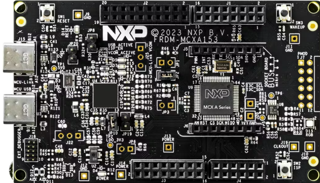
The FRDM-MCXA153 is a development platform manufactured by NXP. It is built around a Kinetis microcontroller, offering a versatile and powerful solution for rapid prototyping and development of embedded applications. This platform is designed to simplify the development process by providing a wide range of connectivity options, sensor interfaces, and peripheral support.
Explore Projects Built with FRDM-MCXA153


Explore Projects Built with FRDM-MCXA153
Common Applications and Use Cases
- IoT (Internet of Things) device prototyping
- Industrial automation and control systems
- Wearable technology development
- Sensor data acquisition and processing
- Educational and research projects in embedded systems
Technical Specifications
The following table outlines the key technical specifications of the FRDM-MCXA153:
| Specification | Details |
|---|---|
| Microcontroller | Kinetis MCU (ARM Cortex-M4 core) |
| Operating Voltage | 3.3V (regulated from USB or external power supply) |
| Input Voltage Range | 5V (via USB) or 7-12V (via external power supply) |
| Clock Speed | Up to 120 MHz |
| Flash Memory | 512 KB |
| RAM | 128 KB |
| Connectivity Interfaces | USB, UART, SPI, I2C, CAN, GPIO |
| Debug Interface | OpenSDA (onboard debug interface for programming and debugging) |
| Expansion Headers | Arduino R3-compatible headers and additional I/O pins |
| Sensor Support | Built-in accelerometer and magnetometer |
| Dimensions | 3.5 x 2.2 inches (approx.) |
Pin Configuration and Descriptions
The FRDM-MCXA153 features multiple pin headers for connectivity. Below is a summary of the pin configuration:
Arduino-Compatible Header
| Pin | Function | Description |
|---|---|---|
| D0-D13 | Digital I/O | General-purpose digital input/output pins |
| A0-A5 | Analog Input | Analog input pins for sensor interfacing |
| 3.3V | Power Output | 3.3V regulated power output |
| 5V | Power Output | 5V regulated power output |
| GND | Ground | Common ground |
| VIN | Power Input | External power input (7-12V) |
Additional I/O Pins
| Pin | Function | Description |
|---|---|---|
| SDA | I2C Data | Data line for I2C communication |
| SCL | I2C Clock | Clock line for I2C communication |
| TX/RX | UART | Transmit/Receive pins for serial communication |
| CAN_H | CAN High | High line for CAN communication |
| CAN_L | CAN Low | Low line for CAN communication |
Usage Instructions
How to Use the FRDM-MCXA153 in a Circuit
Powering the Board:
- Connect the board to a computer via the USB port for power and programming.
- Alternatively, use an external power supply (7-12V) connected to the VIN pin.
Programming the Microcontroller:
- Use the onboard OpenSDA interface to program the microcontroller.
- Compatible IDEs include NXP's MCUXpresso, Keil µVision, and IAR Embedded Workbench.
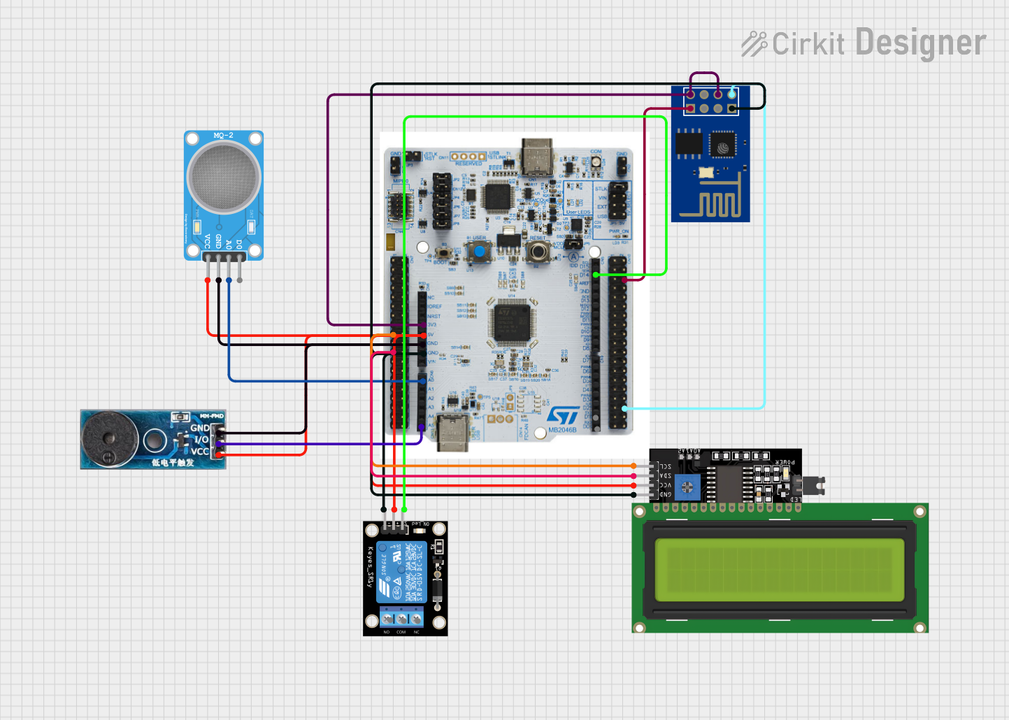
Connecting Peripherals:
- Use the Arduino-compatible headers to connect sensors, actuators, or other modules.
- For I2C devices, connect to the SDA and SCL pins.
- For UART communication, use the TX and RX pins.
Debugging:
- The OpenSDA interface also supports debugging. Connect the board to your computer and use the debugging tools in your IDE.
Important Considerations and Best Practices
- Ensure the input voltage does not exceed the specified range to avoid damaging the board.
- Use proper pull-up resistors for I2C communication if required by your sensors or peripherals.
- Avoid connecting high-current devices directly to the GPIO pins; use external drivers or relays.
- Always check the pinout and voltage levels of connected peripherals to ensure compatibility.
Example: Using the FRDM-MCXA153 with Arduino IDE
The FRDM-MCXA153 can be programmed using the Arduino IDE with the appropriate board support package installed. Below is an example of reading data from the onboard accelerometer:
#include <Wire.h> // Include the I2C library

#define ACCEL_ADDR 0x1D // I2C address of the onboard accelerometer

void setup() {
  Wire.begin(); // Initialize I2C communication
  Serial.begin(9600); // Start serial communication for debugging

  // Configure the accelerometer
  Wire.beginTransmission(ACCEL_ADDR);
  Wire.write(0x2A); // Control register address
  Wire.write(0x01); // Set the accelerometer to active mode
  Wire.endTransmission();

  Serial.println("Accelerometer initialized.");
}

void loop() {
  Wire.beginTransmission(ACCEL_ADDR);
  Wire.write(0x01); // Address of the X-axis data register
  Wire.endTransmission(false);
  Wire.requestFrom(ACCEL_ADDR, 6); // Request 6 bytes (X, Y, Z data)

  if (Wire.available() == 6) {
    int16_t x = (Wire.read() << 8) | Wire.read(); // Combine MSB and LSB
    int16_t y = (Wire.read() << 8) | Wire.read();
    int16_t z = (Wire.read() << 8) | Wire.read();

    Serial.print("X: "); Serial.print(x);
    Serial.print(" Y: "); Serial.print(y);
    Serial.print(" Z: "); Serial.println(z);
  }

  delay(500); // Wait 500ms before the next reading
}
Troubleshooting and FAQs
Common Issues and Solutions
The board is not detected by the computer:
- Ensure the USB cable is properly connected and functional.
- Check if the OpenSDA firmware is up to date.
Unable to program the microcontroller:
- Verify that the correct board and port are selected in your IDE.
- Ensure no other application is using the USB port.
I2C devices are not responding:
- Check the wiring and ensure proper pull-up resistors are used.
- Verify the I2C address of the connected device.
Power issues when using external peripherals:
- Ensure the total current draw does not exceed the board's power supply limits.
- Use an external power source for high-current peripherals.
FAQs
Q: Can I use the FRDM-MCXA153 with other IDEs besides MCUXpresso?
A: Yes, the board is compatible with Keil µVision, IAR Embedded Workbench, and even the Arduino IDE with the appropriate configuration.
Q: Does the board support wireless communication?
A: The FRDM-MCXA153 does not have built-in wireless modules, but you can add Wi-Fi or Bluetooth modules via the expansion headers.
Q: What is the maximum current output of the 3.3V pin?
A: The 3.3V pin can supply up to 100 mA, depending on the input power source.
This documentation provides a comprehensive guide to using the FRDM-MCXA153 for your embedded development needs. For further assistance, refer to the official NXP user manual and resources.