Cirkit Designer
Your all-in-one circuit design IDE
Home /
Component Documentation
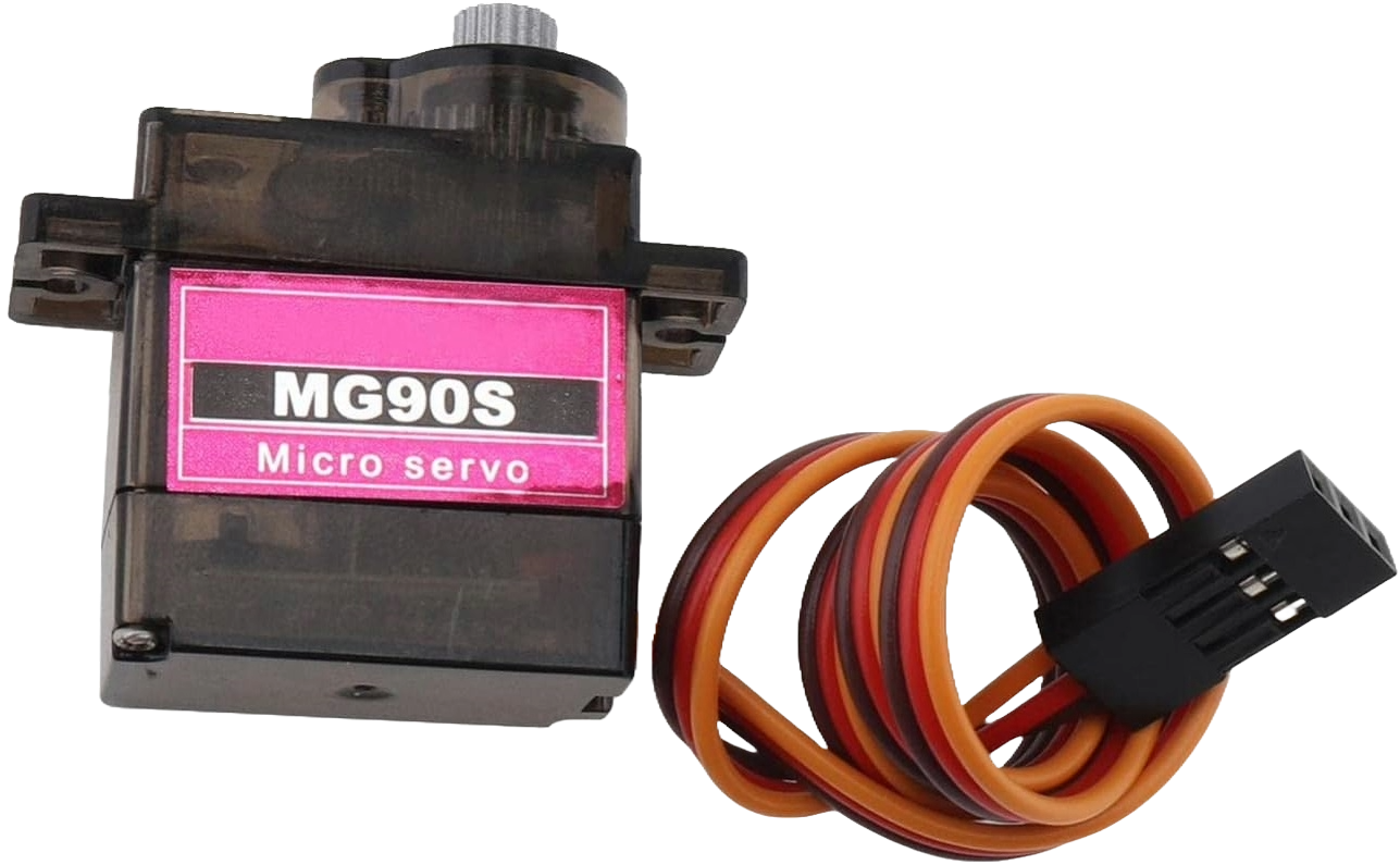
How to Use MG90S: Examples, Pinouts, and Specs
Introduction
The MG90S servo motor is a compact and efficient micro servo often utilized in the field of remote-controlled (RC) models, robotics, and various DIY projects. It is prized for its ability to provide precise control of angular position, speed, and acceleration. The MG90S is known for its high performance relative to its cost, making it a popular choice for hobbyists and educators alike.
Explore Projects Built with MG90S
Arduino Mega 2560-Based Smart Lock System with Servo Control and GSM Connectivity
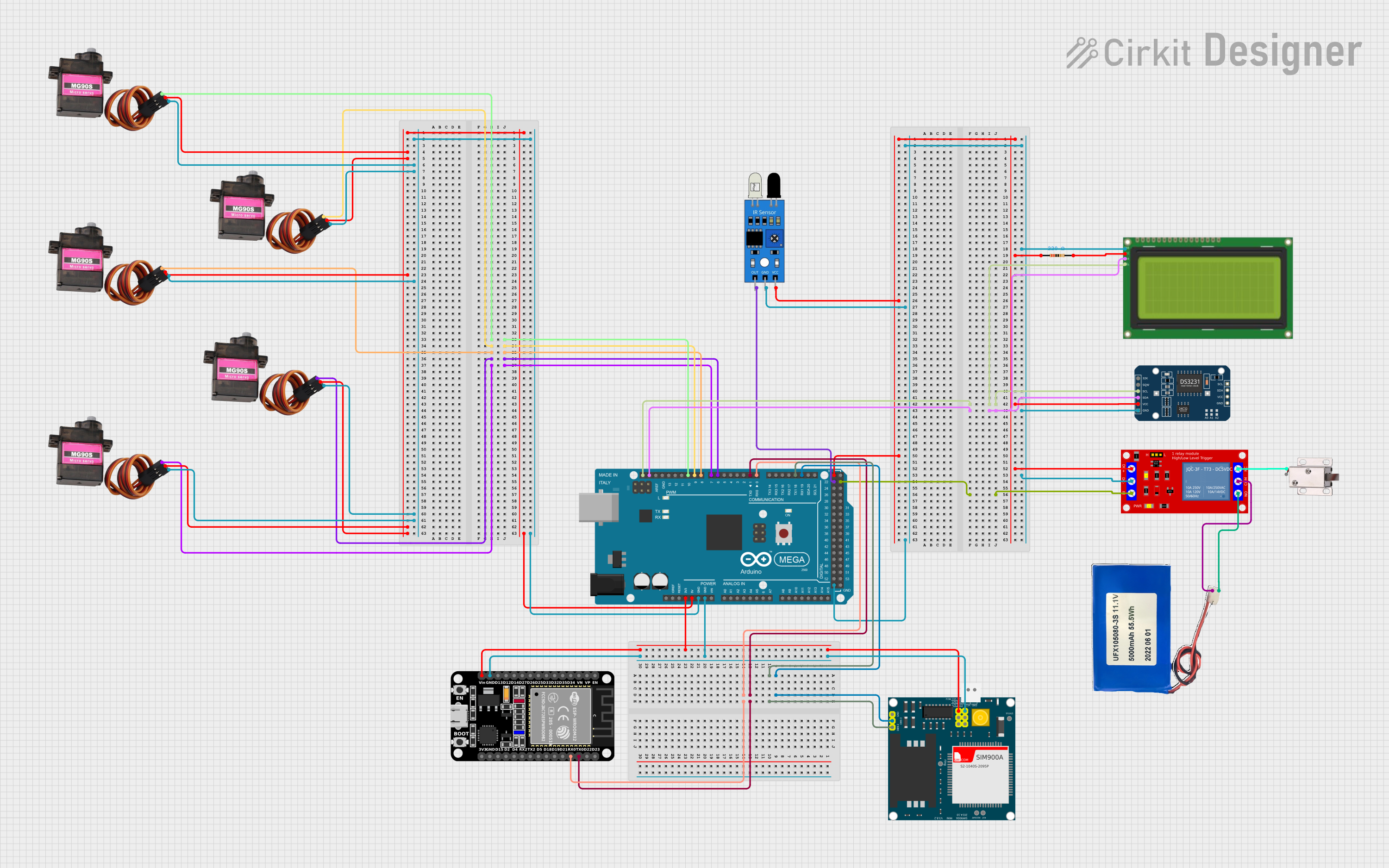
This circuit is a control system utilizing an Arduino Mega 2560 to manage multiple MG90S servos, an LCD display, a DS3231 RTC module, a SIM900A GSM module, and an ESP32 for communication. It also includes a relay module to control a 12V solenoid lock, an IR sensor for input, and a Li-ion battery for power supply.
GPS-Enabled Telemetry Drone with Speedybee F405 WING and Brushless Motor

This circuit is designed for a remote-controlled vehicle or drone, featuring a flight controller that manages a brushless motor, servomotors for actuation, telemetry for data communication, and a GPS module for positioning. It is powered by a lipo battery and includes a receiver for remote control inputs.
Itsy Bitsy M0 Express Controlled Multi-Servo System
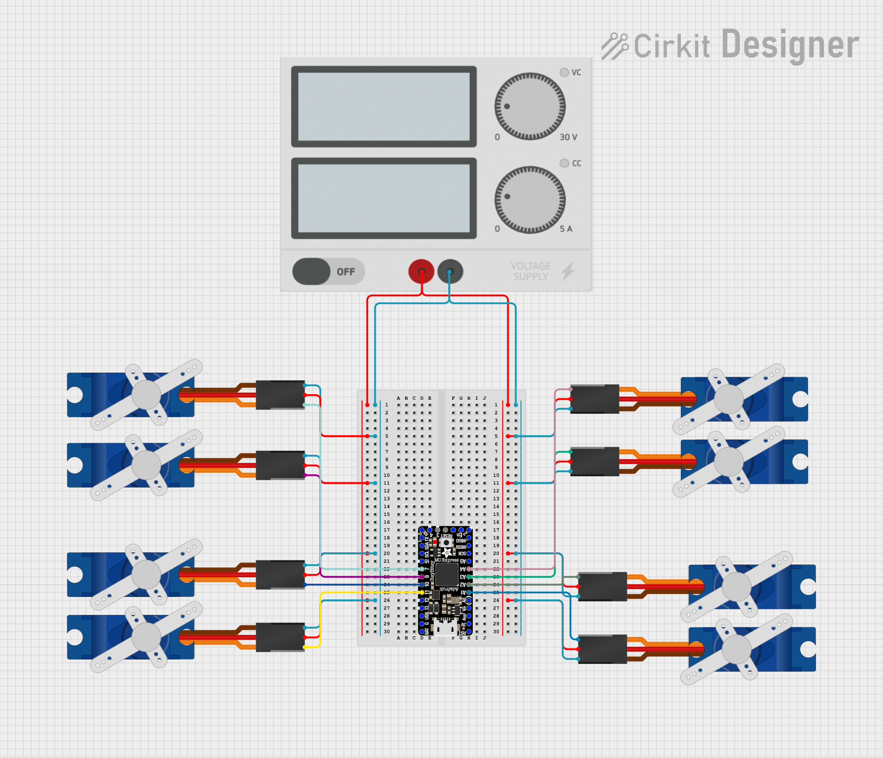
This circuit consists of an Itsy Bitsy M0 Express microcontroller connected to eight Tower Pro SG90 servos. Each servo is controlled by a different digital or analog output pin on the microcontroller. A single power supply provides +5V and GND to all servos, and the microcontroller is configured with some of its pins interconnected for potential programming or operational purposes.
ESP8266 NodeMCU-Based Sensor Monitoring System
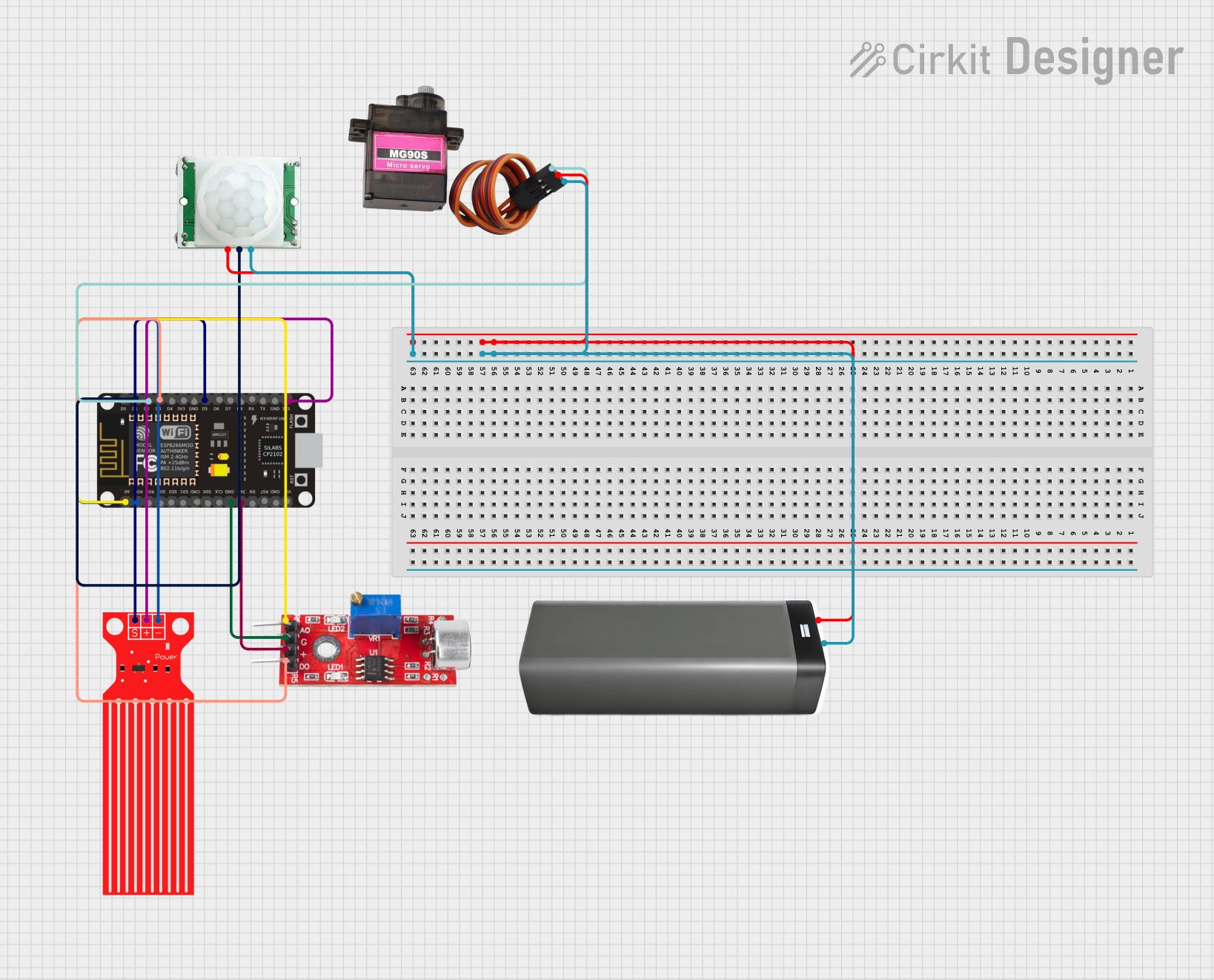
This circuit is designed around an ESP8266 NodeMCU microcontroller, which interfaces with a variety of sensors and a servo motor. It includes a PIR motion sensor to detect movement, a sound sensor for audio detection, and a water level sensor for monitoring liquid levels. The MG90S servo motor is controlled by the microcontroller, and the entire system is powered by a battery pack.
Explore Projects Built with MG90S
Arduino Mega 2560-Based Smart Lock System with Servo Control and GSM Connectivity
This circuit is a control system utilizing an Arduino Mega 2560 to manage multiple MG90S servos, an LCD display, a DS3231 RTC module, a SIM900A GSM module, and an ESP32 for communication. It also includes a relay module to control a 12V solenoid lock, an IR sensor for input, and a Li-ion battery for power supply.
GPS-Enabled Telemetry Drone with Speedybee F405 WING and Brushless Motor
This circuit is designed for a remote-controlled vehicle or drone, featuring a flight controller that manages a brushless motor, servomotors for actuation, telemetry for data communication, and a GPS module for positioning. It is powered by a lipo battery and includes a receiver for remote control inputs.
Itsy Bitsy M0 Express Controlled Multi-Servo System
This circuit consists of an Itsy Bitsy M0 Express microcontroller connected to eight Tower Pro SG90 servos. Each servo is controlled by a different digital or analog output pin on the microcontroller. A single power supply provides +5V and GND to all servos, and the microcontroller is configured with some of its pins interconnected for potential programming or operational purposes.
ESP8266 NodeMCU-Based Sensor Monitoring System
This circuit is designed around an ESP8266 NodeMCU microcontroller, which interfaces with a variety of sensors and a servo motor. It includes a PIR motion sensor to detect movement, a sound sensor for audio detection, and a water level sensor for monitoring liquid levels. The MG90S servo motor is controlled by the microcontroller, and the entire system is powered by a battery pack.
Common Applications and Use Cases
- Radio-controlled vehicles (cars, airplanes, boats)
- Robotic arms and manipulators
- Automated doors and windows
- Camera pan/tilt systems
- Educational projects and demonstrations
Technical Specifications
Key Technical Details
- Voltage: 4.8V to 6.0V
- Stall Torque: 2.0 kg-cm (4.8V), 2.2 kg-cm (6.0V)
- Operating Speed: 0.10 sec/60° (4.8V), 0.08 sec/60° (6.0V)
- Temperature Range: -30°C to +60°C
- Weight: 13.4g
- Dimensions: 22.8 x 12.2 x 28.5 mm
Pin Configuration and Descriptions
| Pin Number | Color | Function |
|---|---|---|
| 1 | Brown | Ground (GND) |
| 2 | Red | Power (VCC) |
| 3 | Orange | Control Signal |
Usage Instructions
How to Use the MG90S in a Circuit
- Power Supply: Connect the red wire to a power supply within the specified voltage range (4.8V to 6.0V). Ensure that the power supply can deliver sufficient current for the servo's operation.
- Ground Connection: Attach the brown wire to the ground of your power supply and the ground of your control board to ensure a common reference point.
- Control Signal: Connect the orange wire to a PWM-capable pin on your control board (e.g., an Arduino UNO).
Important Considerations and Best Practices
- Avoid stalling the servo motor for extended periods, as this can lead to overheating and damage.
- Ensure that the mechanical load does not exceed the servo's stall torque rating.
- Use a servo driver or shield when controlling multiple servos to prevent excessive current draw from the control board.
- Implement proper gear alignment to prevent unnecessary strain on the servo's internal gears.
Example Code for Arduino UNO
#include <Servo.h>

Servo myservo;  // Create servo object to control the MG90S

void setup() {
  myservo.attach(9);  // Attaches the servo on pin 9 to the servo object
}

void loop() {
  myservo.write(90);  // Set servo to mid-point (90 degrees)
  delay(1000);        // Wait for 1 second
  myservo.write(0);   // Move servo to 0 degrees
  delay(1000);        // Wait for 1 second
  myservo.write(180); // Move servo to 180 degrees
  delay(1000);        // Wait for 1 second
}
Troubleshooting and FAQs
Common Issues
- Servo not responding: Ensure that all connections are secure and the power supply is within the specified voltage range.
- Erratic movement: Check for any signal interference or inconsistencies in the control signal.
- Overheating: Reduce the load or duty cycle if the servo motor becomes too hot to touch.
Solutions and Tips for Troubleshooting
- Double-check wiring, especially the orientation of the control signal wire.
- Use an external power supply for the servo if the Arduino UNO cannot provide sufficient current.
- Implement a "sweep" test code to ensure the servo is functioning correctly across its range of motion.
FAQs
Q: Can I control the MG90S servo with a Raspberry Pi? A: Yes, but you will need to ensure proper logic level conversion and use a library that supports PWM output.
Q: How can I increase the lifespan of my MG90S servo? A: Avoid excessive loads, operate within the recommended voltage range, and ensure proper alignment of connected components.