How to Use fpga: Examples, Pinouts, and Specs
Introduction
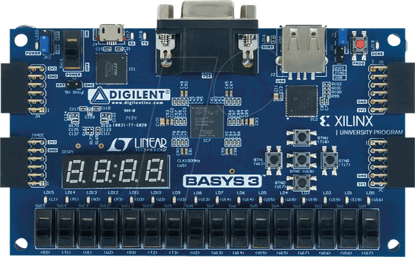
The XINIX Basys 3 is a Field-Programmable Gate Array (FPGA) development board designed for beginners and professionals to implement custom digital circuits. FPGAs are integrated circuits that can be programmed by the user after manufacturing, enabling the creation of custom hardware designs for a wide range of applications. The Basys 3 is based on the Xilinx Artix-7 FPGA and is equipped with various peripherals, making it ideal for learning, prototyping, and implementing digital systems.
Explore Projects Built with fpga


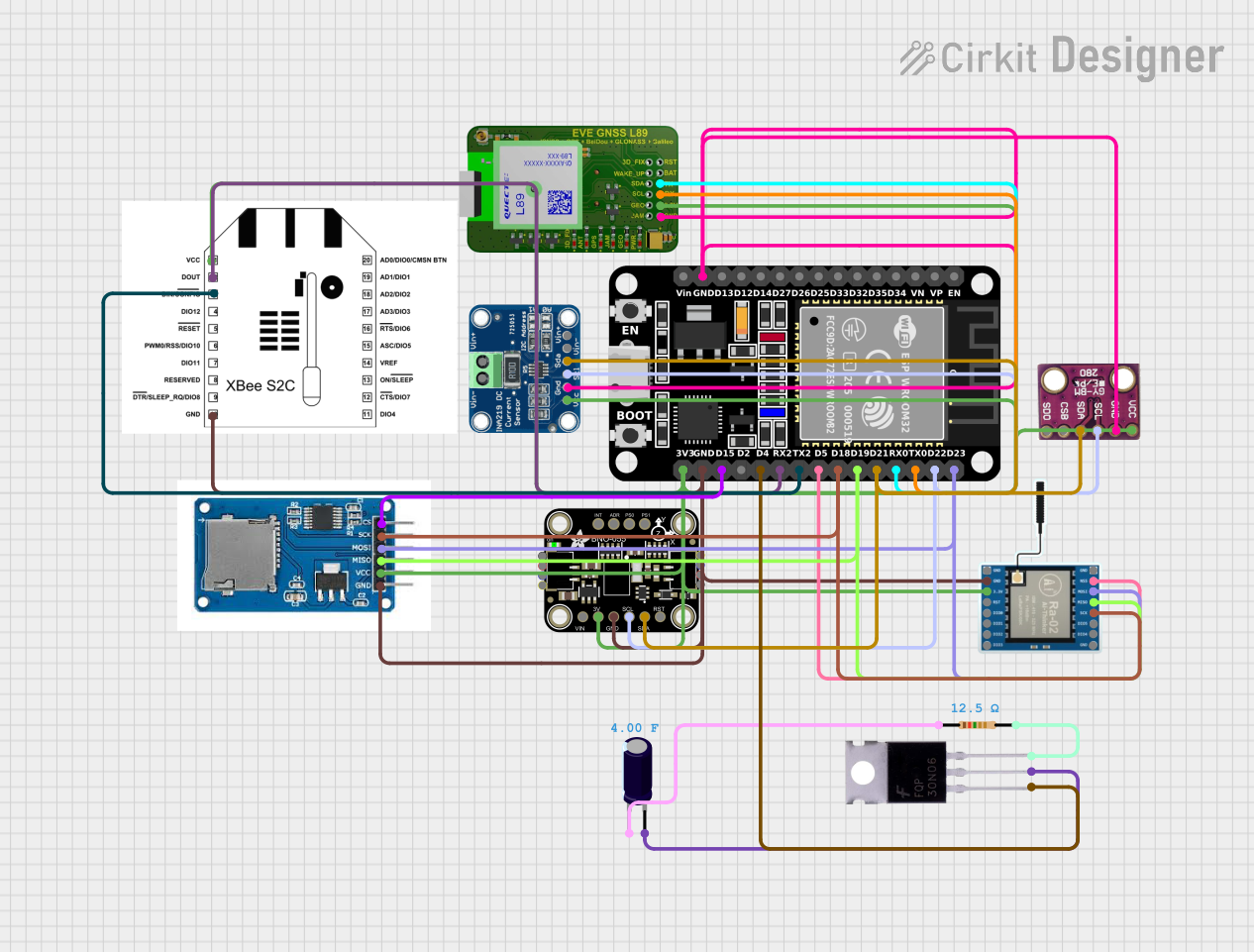
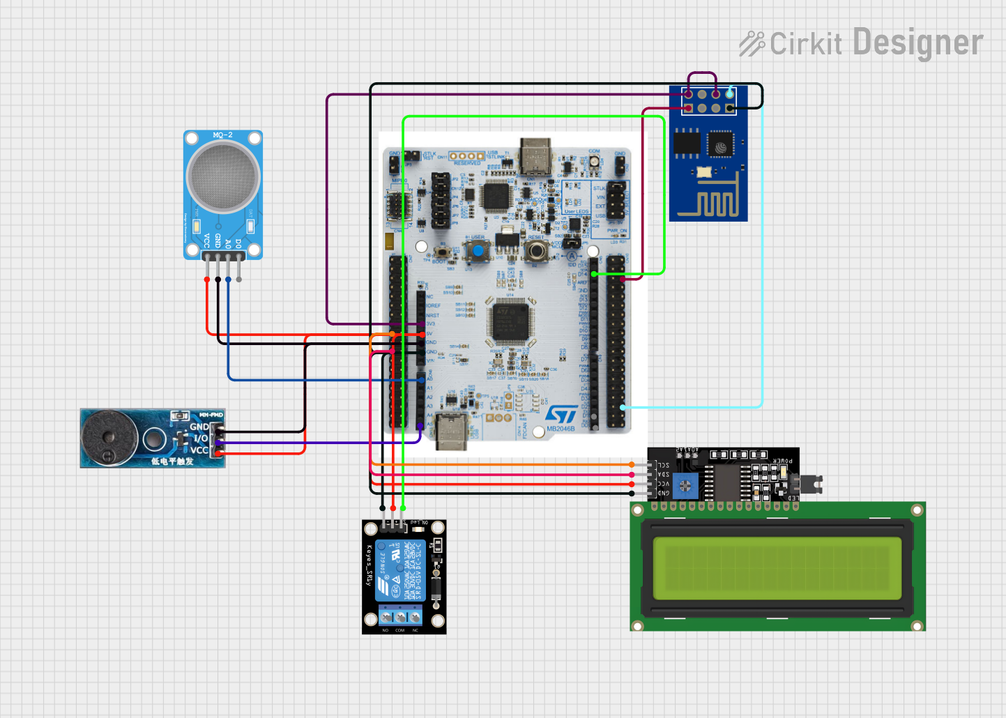
Explore Projects Built with fpga
Common Applications and Use Cases
- Digital signal processing (DSP)
- Custom processor design
- Hardware acceleration for algorithms
- Robotics and automation systems
- Educational purposes for learning digital design
- Prototyping and testing of digital circuits
Technical Specifications
The XINIX Basys 3 FPGA board is built around the Xilinx Artix-7 FPGA (XC7A35T-1CPG236C). Below are the key technical details and pin configurations:
Key Technical Details
| Specification | Value |
|---|---|
| FPGA Model | Xilinx Artix-7 (XC7A35T-1CPG236C) |
| Logic Cells | 33,280 |
| Flip-Flops | 41,600 |
| Look-Up Tables (LUTs) | 20,800 |
| Block RAM | 1,800 Kb |
| Clock Speed | 100 MHz onboard oscillator |
| I/O Pins | 16 user switches, 16 LEDs, 5 push buttons |
| Communication Interfaces | USB, UART, SPI, I2C |
| Power Supply | 5V via USB or external power supply |
| Programming Interface | USB-JTAG |
Pin Configuration and Descriptions
The Basys 3 board provides a variety of I/O pins and peripherals. Below is a summary of the key pin configurations:
User I/O Pins
| Pin Name | Description |
|---|---|
| SW0 - SW15 | 16 user-configurable switches |
| LED0 - LED15 | 16 user-configurable LEDs |
| BTN0 - BTN4 | 5 push buttons for user input |
| JA, JB, JC, JD | 4 Pmod connectors for external I/O |
Power and Communication Pins
| Pin Name | Description |
|---|---|
| USB | USB port for power and programming |
| JTAG | JTAG interface for FPGA programming |
| VCC | 3.3V and 5V power supply pins |
| GND | Ground pins |
Usage Instructions
The XINIX Basys 3 FPGA board is versatile and easy to use for implementing custom digital designs. Below are the steps and best practices for using the board:
How to Use the Component in a Circuit
- Power the Board: Connect the Basys 3 to your computer using the USB cable or an external 5V power supply.
- Install Software: Download and install Xilinx Vivado Design Suite, which is used for programming the FPGA.
- Create a Design:
- Open Vivado and create a new project.
- Write your design in a hardware description language (HDL) such as Verilog or VHDL.
- Simulate and verify your design using Vivado's built-in tools.
- Program the FPGA:
- Connect the Basys 3 to your computer via USB.
- Use Vivado to generate a bitstream file (.bit) and program the FPGA.
- Test Your Design: Use the onboard switches, LEDs, and buttons to interact with your design.
Important Considerations and Best Practices
- Clock Management: Use the onboard 100 MHz oscillator or configure a custom clock using the Clocking Wizard in Vivado.
- Voltage Levels: Ensure that external devices connected to the Pmod connectors operate at 3.3V logic levels.
- Static Protection: Handle the board with care to avoid damage from electrostatic discharge (ESD).
- Resource Utilization: Monitor the usage of logic cells, LUTs, and block RAM to ensure your design fits within the FPGA's capacity.
Example Code for an LED Blinking Circuit
Below is an example Verilog code to blink an LED on the Basys 3 board:
// Simple LED Blinking Example for Basys 3
module led_blink(
    input wire clk,       // 100 MHz clock input
    output reg led        // Output to LED
);

    reg [26:0] counter;   // 27-bit counter for clock division

    always @(posedge clk) begin
        counter <= counter + 1; // Increment counter on each clock cycle
        if (counter == 27'd100_000_000) begin
            // Toggle LED every 1 second (assuming 100 MHz clock)
            led <= ~led;
            counter <= 0;       // Reset counter
        end
    end
endmodule
To use this code:
- Create a new project in Vivado.
- Add the above Verilog code as a source file.
- Assign the
ledoutput to one of the onboard LEDs (e.g.,LED0). - Generate the bitstream and program the FPGA.
Troubleshooting and FAQs
Common Issues Users Might Face
FPGA Not Programming:
- Ensure the USB cable is properly connected.
- Verify that the correct FPGA part number is selected in Vivado.
- Check if the board is powered on.
Design Not Working as Expected:
- Double-check the pin assignments in your design constraints file (.xdc).
- Simulate your design in Vivado to identify potential logic errors.
Overheating:
- Avoid overloading the FPGA with excessive current draw.
- Ensure proper ventilation around the board.
External Devices Not Responding:
- Verify that external devices are compatible with 3.3V logic levels.
- Check the connections to the Pmod connectors.
Solutions and Tips for Troubleshooting
- Use the onboard LEDs and switches for debugging by assigning them to key signals in your design.
- Refer to the Basys 3 reference manual for detailed information on pin mappings and board features.
- Update the Vivado software to the latest version to ensure compatibility with the Basys 3 board.
By following this documentation, users can effectively utilize the XINIX Basys 3 FPGA board for a wide range of digital design applications.