Cirkit Designer
Your all-in-one circuit design IDE
Home /
Component Documentation
How to Use CD74HC4067: Examples, Pinouts, and Specs
Introduction
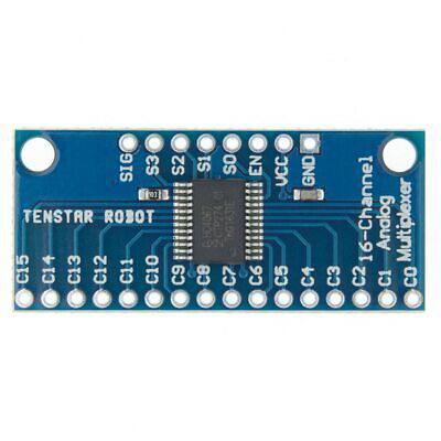
The CD74HC4067 is a versatile 16-channel analog multiplexer/demultiplexer. It features a digital control interface that allows one of 16 inputs to be connected to a single output. This component is widely used in applications requiring multiple analog or digital signals to be routed to a single point, such as in data acquisition systems, signal routing, and sensor multiplexing.
Explore Projects Built with CD74HC4067
Arduino Micro-Based Multi-Channel Analog Input System with Potentiometers and Toggle Switches

This circuit features an Arduino Micro connected to three CD74HC4067 multiplexers, which are used to expand the number of analog inputs. Multiple potentiometers and toggle switches are connected to the multiplexers, allowing the Arduino to read various analog signals and switch states for further processing.
STM32-Controlled LED Display with 74HC595 Shift Register and 12-Bit DAC

This circuit uses a 74HC595 shift register to control multiple LEDs via a common ground configuration, with a microcontroller providing serial data input. It includes decoupling capacitors for stability and a 12-Bit DAC, potentially for analog signal generation or reference voltage application.
Teensy 4.0 and MAX7219-Based 7-Segment Display Counter

This circuit uses a Teensy 4.0 microcontroller to control a MAX7219 LED driver, which in turn drives three 7-segment displays. The microcontroller runs code to display numbers from 0 to 999 on the 7-segment displays, with the SN74AHCT125N buffer providing signal integrity and the necessary capacitors and resistors ensuring stable operation.
Teensy 4.1-Based Multi-Channel Potentiometer Interface with 74HC4051 Mux and AMS1117 3.3V Regulator

This circuit features a Teensy 4.1 microcontroller interfaced with a SparkFun 74HC4051 8-channel multiplexer to read multiple rotary potentiometers. The AMS1117 3.3V voltage regulator provides a stable 3.3V supply to the multiplexer and potentiometers, while electrolytic and ceramic capacitors are used for power supply filtering and stabilization.
Explore Projects Built with CD74HC4067
Arduino Micro-Based Multi-Channel Analog Input System with Potentiometers and Toggle Switches
This circuit features an Arduino Micro connected to three CD74HC4067 multiplexers, which are used to expand the number of analog inputs. Multiple potentiometers and toggle switches are connected to the multiplexers, allowing the Arduino to read various analog signals and switch states for further processing.
STM32-Controlled LED Display with 74HC595 Shift Register and 12-Bit DAC
This circuit uses a 74HC595 shift register to control multiple LEDs via a common ground configuration, with a microcontroller providing serial data input. It includes decoupling capacitors for stability and a 12-Bit DAC, potentially for analog signal generation or reference voltage application.
Teensy 4.0 and MAX7219-Based 7-Segment Display Counter
This circuit uses a Teensy 4.0 microcontroller to control a MAX7219 LED driver, which in turn drives three 7-segment displays. The microcontroller runs code to display numbers from 0 to 999 on the 7-segment displays, with the SN74AHCT125N buffer providing signal integrity and the necessary capacitors and resistors ensuring stable operation.
Teensy 4.1-Based Multi-Channel Potentiometer Interface with 74HC4051 Mux and AMS1117 3.3V Regulator
This circuit features a Teensy 4.1 microcontroller interfaced with a SparkFun 74HC4051 8-channel multiplexer to read multiple rotary potentiometers. The AMS1117 3.3V voltage regulator provides a stable 3.3V supply to the multiplexer and potentiometers, while electrolytic and ceramic capacitors are used for power supply filtering and stabilization.
Common Applications
- Data acquisition systems
- Signal routing
- Sensor multiplexing
- Audio signal switching
- Test equipment
Technical Specifications
Key Technical Details
| Parameter | Value |
|---|---|
| Supply Voltage | 2V to 6V |
| Input Voltage | 0V to Vcc |
| On-State Resistance | 70Ω (typical) at Vcc = 4.5V |
| Propagation Delay | 6ns (typical) at Vcc = 5V |
| Control Inputs | 4-bit binary (S0, S1, S2, S3) |
| Enable Input | Active Low (EN) |
| Operating Temperature | -55°C to 125°C |
Pin Configuration and Descriptions
| Pin No. | Name | Description |
|---|---|---|
| 1 | S1 | Control Input 1 |
| 2 | S2 | Control Input 2 |
| 3 | S3 | Control Input 3 |
| 4 | S4 | Control Input 4 |
| 5 | Z | Common Output/Input |
| 6 | Y15 | Channel 15 Input/Output |
| 7 | Y14 | Channel 14 Input/Output |
| 8 | Y13 | Channel 13 Input/Output |
| 9 | Y12 | Channel 12 Input/Output |
| 10 | Y11 | Channel 11 Input/Output |
| 11 | Y10 | Channel 10 Input/Output |
| 12 | Y9 | Channel 9 Input/Output |
| 13 | Y8 | Channel 8 Input/Output |
| 14 | Y7 | Channel 7 Input/Output |
| 15 | Y6 | Channel 6 Input/Output |
| 16 | Y5 | Channel 5 Input/Output |
| 17 | Y4 | Channel 4 Input/Output |
| 18 | Y3 | Channel 3 Input/Output |
| 19 | Y2 | Channel 2 Input/Output |
| 20 | Y1 | Channel 1 Input/Output |
| 21 | Y0 | Channel 0 Input/Output |
| 22 | EN | Enable Input (Active Low) |
| 23 | Vcc | Supply Voltage |
| 24 | GND | Ground |
Usage Instructions
How to Use the Component in a Circuit
- Power Supply: Connect the Vcc pin to a power supply (2V to 6V) and the GND pin to ground.
- Control Inputs: Connect the control inputs (S0, S1, S2, S3) to a microcontroller or other digital control circuit to select the desired channel.
- Enable Input: Connect the EN pin to ground to enable the multiplexer. If the EN pin is high, the multiplexer is disabled.
- Signal Connections: Connect the desired input signals to the Y0-Y15 pins. The selected input will be routed to the Z pin.
Important Considerations and Best Practices
- Ensure that the input voltage on the Y0-Y15 pins does not exceed the supply voltage (Vcc).
- Use decoupling capacitors close to the Vcc pin to reduce noise and improve stability.
- When switching between channels, allow a small delay to ensure the signal has settled before reading the output.
Example: Connecting to an Arduino UNO
// Example code to use CD74HC4067 with Arduino UNO

const int S0 = 2; // Control pin S0 connected to Arduino pin 2
const int S1 = 3; // Control pin S1 connected to Arduino pin 3
const int S2 = 4; // Control pin S2 connected to Arduino pin 4
const int S3 = 5; // Control pin S3 connected to Arduino pin 5
const int EN = 6; // Enable pin connected to Arduino pin 6
const int Z = A0; // Common output connected to Arduino analog pin A0

void setup() {
  pinMode(S0, OUTPUT);
  pinMode(S1, OUTPUT);
  pinMode(S2, OUTPUT);
  pinMode(S3, OUTPUT);
  pinMode(EN, OUTPUT);
  digitalWrite(EN, LOW); // Enable the multiplexer
  Serial.begin(9600);
}

void loop() {
  for (int channel = 0; channel < 16; channel++) {
    selectChannel(channel);
    int value = analogRead(Z); // Read the value from the selected channel
    Serial.print("Channel ");
    Serial.print(channel);
    Serial.print(": ");
    Serial.println(value);
    delay(500); // Wait for 500ms before reading the next channel
  }
}

void selectChannel(int channel) {
  digitalWrite(S0, channel & 0x01);
  digitalWrite(S1, (channel >> 1) & 0x01);
  digitalWrite(S2, (channel >> 2) & 0x01);
  digitalWrite(S3, (channel >> 3) & 0x01);
}
Troubleshooting and FAQs
Common Issues
No Signal Output:
- Ensure the EN pin is connected to ground to enable the multiplexer.
- Verify that the control inputs (S0, S1, S2, S3) are correctly set to select the desired channel.
Incorrect Channel Selection:
- Check the connections of the control inputs to the microcontroller.
- Ensure the control signals are correctly set according to the desired channel.
Signal Distortion or Noise:
- Use decoupling capacitors close to the Vcc pin.
- Ensure the input signals do not exceed the supply voltage (Vcc).
Solutions and Tips for Troubleshooting
- Verify Connections: Double-check all connections to ensure they are correct and secure.
- Check Power Supply: Ensure the power supply voltage is within the specified range (2V to 6V).
- Use Proper Grounding: Ensure a good ground connection to minimize noise and signal distortion.
- Delay Between Channel Switching: Allow a small delay when switching between channels to ensure the signal has settled before reading the output.
By following these guidelines and best practices, you can effectively use the CD74HC4067 in your projects and applications.